Current limiter using transistor not working as expected

Thread Starter

The Engineer

Joined Sep 3, 2014
35
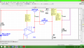
I have created a voltage regulation circuit using op amp and feedback resistors, now I am trying to add a current limiter to the circuit. have read how to create this using two transistors and a resistor.
So far I know that if the current is to be limited at 10mA, and the transistor base emitter saturation voltage is 0.65V, then I choose a value for resistance using 0.65/0.01 = 65Ω.
current limiter not working.png current limiter not working2.png
at first this seems to work, however when I lower the load resistance, allowing more current to flow, the current is not limiting. I have read into it and followed the steps to create this circuit so I am now confused as to why this will not work the way it should.
If anybody can supply me with a reason as to why this is not doing its job that would be great !
-Con
 

joeyd999

Joined Jun 6, 2011
5,234
I think you've got the collector/emitter switched...

Edit: and you should also have a current limiting resistor on the output of the 741.
 

Thread Starter

The Engineer

Joined Sep 3, 2014
35
I think you've got the collector/emitter switched...

Edit: and you should also have a current limiting resistor on the output of the 741.
Okay ! il switch that over and report back asap, in regards to the current limiter.. the maximum base current for the 2n2222a as specified in the datasheet is 6V, and in this circuit that requires a 150K resistor ! So i left that out until i next see my lecturer as this figure seems far too high ! or would you say that sounds plausible ?
 

WBahn

Joined Mar 31, 2012
29,978
Also i did not think it mattered which way collector and emitter are as long as the base is connected correctly !
On nearly all BJTs there is a very significant between the emitter and the collector. The physical layout is very different in order to achieve different properties. The goal is often to achieve high forward voltage gain by also high breakdown voltages. If you swap the roles of such a transistor, you usually get crappy current gain and much lower breakdown voltages.

In the case of a FET, those tend to be much more symmetric and, in an IC circuit, are often truly symmetric and the drain and source are interchangeable.
 

Thread Starter

The Engineer

Joined Sep 3, 2014
35
I don't even know what it means for a maximum current to be specified as being a particular voltage.
Terribly sorry that was a typo, the emitter base breakdown voltage of the 2n2222a is rated 6V, in order to keep the base below this voltage I tested a range of resistorscurrent limiter not working show resistor.png a 150K resistor will keep to voltage at the base to 5.72 (0.28V below B-E breakdown voltage). however this seems to be very high resistor value.

In regards to the current limiter not working as it should the following image shows a load of 300 ohms, and all though current has been set to 10mA using 65Ω resistor (0.65/0.01), the current at the load still exceeds this amount.
 

Attachments

joeyd999

Joined Jun 6, 2011
5,234
Forget about the reverse emitter-base breakdown voltage. It doesn't come into play in this circuit.

Q1 is always forward biased, and Q2 is either off (0 < Vbe < ~0.7V) or conducting (Vbe >= ~0.7V). Vbe of either transistor will never be negative, or exceed -6V.

The function of Q2 is to steal base current from Q1 and shunt it into the load when the voltage across RF1 exceeds the turn-on Vbe voltage. This voltage is an approximation, and varies with temperature and Ic. So, don't expect a hard limit.

The last image shows the output of the 741 directly tied to the collector of Q2. Therefore, when Q2 is conducting, the full current capacity of the 741 is available to the load. The 741 is easily capable of supplying tens of milliamps to the load by itself, thus negating any reduction in the Q1 emitter current.

R1 needs to be directly on the output of the 741, and the collector of Q2 tied directly to the base of Q1. R1 needs to be sized so that it can provide approximately 1mA to the base of Q1 under worst case conditions (you have only 1.8V of headroom with your 12V supply and the 741 output swing eats all of that, so, this circuit will never really work). That current will then be shunted into the load, effectively shutting off Q2's capability of supplying current.

But, again, this will not work at at 10.2 V with a supply voltage of 12V.
 

Jony130

Joined Feb 17, 2009
5,487
Terribly sorry that was a typo, the emitter base breakdown voltage of the 2n2222a is rated 6V, in order to keep the base below this voltage I tested a range of resistors a 150K resistor will keep to voltage at the base to 5.72 (0.28V below B-E breakdown voltage). however this seems to be very high resistor value.
View attachment 79455
You really need to back to basics. Because you even do not understand how BJT work. And wrongly understand the data sheet.
Do you even know the differences between Emitter Base voltage and Base Emitter Voltage ?

In regards to the current limiter not working as it should the following image shows a load of 300 ohms, and all though current has been set to 10mA using 65Ω resistor (0.65/0.01), the current at the load still exceeds this amount.
So you assume that Vbe is constant ??
 

Thread Starter

The Engineer

Joined Sep 3, 2014
35
On nearly all BJTs there is a very significant between the emitter and the collector. The physical layout is very different in order to achieve different properties. The goal is often to achieve high forward voltage gain by also high breakdown voltages. If you swap the roles of such a transistor, you usually get crappy current gain and much lower breakdown voltages.

In the case of a FET, those tend to be much more symmetric and, in an IC circuit, are often truly symmetric and the drain and source are interchangeable.
Okay I see what you mean here ! im going to try using FETs instead of the 2n2222a , and see if there are any improvements :)
 

Thread Starter

The Engineer

Joined Sep 3, 2014
35
R1 needs to be directly on the output of the 741, and the collector of Q2 tied directly to the base of Q1. R1 needs to be sized so that it can provide approximately 1mA to the base of Q1 under worst case conditions (you have only 1.8V of headroom with your 12V supply and the 741 output swing eats all of that, so, this circuit will never really work). That current will then be shunted into the load, effectively shutting off Q2's capability of supplying current.

But, again, this will not work at at 10.2 V with a supply voltage of 12V.
I have modified the circuit slightly, looking at my notes I have drawn them incorrectly regarding the location of the Q1 protection resistor !

Why do you choose the value of 1mA of the base of the transistor ? No matter what value of resistor I choose I cannot raise the node supplying the base current of each transistor higher than 47.3uA.

Also how did you calculate the 1.8V of "headroom" ? do you mean the remaining available voltage in the circuit ?
my apologies ! I am not familiar with this. "the 741 output swing eats all of that, so, this circuit will never really work", I do not follow what you mean at this point.

I have added am image of the current setup with the resistor moved to the correct place ! current limiter not working resistor moved to crrect place.png
 

joeyd999

Joined Jun 6, 2011
5,234
Your input voltage is 12VDC. Your desired output voltage is 10.2VDC (5.1VDC * 2). 12-10.2=1.8.

The voltage drop of the Q1 emitter follower is going to be roughly 0.7V, meaning that the output of the amp will have to be at least 10.9V (ignoring any voltage drop in R1), leaving only 1.1V margin from the top supply rail. The 741 cannot do this. Either raise your supply voltage, or lower the regulated output voltage.

1mA base current (or 1/10 of the max load current) is a rule of thumb. 1 mA will be supplied via the 741 through R1, and the remainder, 9mA, will be supplied by the transistor.

For such a low output current, the 1/10 is very conservative -- you might be able to get away with 1/20 or 1/50. But 48uA (1/208) will not cut it -- even with a beta of 200.
 

WBahn

Joined Mar 31, 2012
29,978
Okay I see what you mean here ! im going to try using FETs instead of the 2n2222a , and see if there are any improvements :)
There's nothing wrong with using a BJT (I don't know that the 2N2222 is a particularly good choice, but if not there are plenty that would be). Just use it correctly making the proper distinction between collector and emitter.

Plus, individual FETs are seldom symmetric because the body connection is almost always hard tied to the source pin and so reversing the drain and source connections has the potential to turn on the parasitic diode that exists there.
 

WBahn

Joined Mar 31, 2012
29,978
I have modified the circuit slightly, looking at my notes I have drawn them incorrectly regarding the location of the Q1 protection resistor !

Why do you choose the value of 1mA of the base of the transistor ? No matter what value of resistor I choose I cannot raise the node supplying the base current of each transistor higher than 47.3uA.

Also how did you calculate the 1.8V of "headroom" ? do you mean the remaining available voltage in the circuit ?
my apologies ! I am not familiar with this. "the 741 output swing eats all of that, so, this circuit will never really work", I do not follow what you mean at this point.

I have added am image of the current setup with the resistor moved to the correct place ! View attachment 79470
The reason why you still do not understand the significance of the headroom is because you won't do what I recommended all the way back in the first handful of posts in the original thread. Run a simulation that plots the output characteristic of the opamp so that you can get a feel for how it behaves and what it will and won't do.
 

Thread Starter

The Engineer

Joined Sep 3, 2014
35
Your input voltage is 12VDC. Your desired output voltage is 10.2VDC (5.1VDC * 2). 12-10.2=1.8.

The voltage drop of the Q1 emitter follower is going to be roughly 0.7V, meaning that the output of the amp will have to be at least 10.9V (ignoring any voltage drop in R1), leaving only 1.1V margin from the top supply rail. The 741 cannot do this. Either raise your supply voltage, or lower the regulated output voltage.

1mA base current (or 1/10 of the max load current) is a rule of thumb. 1 mA will be supplied via the 741 through R1, and the remainder, 9mA, will be supplied by the transistor.

For such a low output current, the 1/10 is very conservative -- you might be able to get away with 1/20 or 1/50. But 48uA (1/208) will not cut it -- even with a beta of 200.
Ok so now i see I need to leave at least 2V rather than 1.1 for the op amp to operate properly, I am required to use a 5V zener so that must stay fixed. I have lowered the gain to 1.5, however I am still getting an output voltage of 11.1V at the output of the op amp !

also although I higher base current is reuired, the current at the base of the transistors seems to be fixed, I have changed the value of the current protection resistor, changed the resistance of the load, changed the voltage source, none of these have hardly changed the base current atall, no where near to 1mA anyway. there must be something I am missing here ?current limiter not working base current wont exeed uA .png
 
Top