Current limiter using mosfets

Thread Starter

newbies_hobbyist

Joined Jun 4, 2010
85
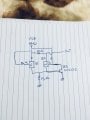
Hi. I am planning to limit the current from my laptop USB port. I want to limit it to 330mA only using two mosfet and one transistor. My idea of the circuit is in the attachment. The way how I want it to work is when the the current is less than 330mA Q1 and Q2 both on but when my load draw more than 330mA then Q2 will switch off with the help of Q3 and the current to my load will be limited to 250mA only. When the current goes back to normal then Q3 will switch off and Q2 switch on again. I need your help what am I missing here.

thanks
 

Attachments

Thread Starter

newbies_hobbyist

Joined Jun 4, 2010
85
hi nh,
Have you calculated the voltage drop across the 20R when you try to draw 330mA.??
E
Hi eric,

I did not calculate it yet, I just draw it to show how I want the circuit to function. Well in fact I want that 20ohm to be in shunt between Q1 drain and source when the current is less than 330ma.
 

ericgibbs

Joined Jan 29, 2010
18,767
hi,
The problem is you will have a voltage loss across the current limiting circuit, so it will not maintain a 5V at the the load.
Why are you requiring to limit the current, into what device.?

E
 

Thread Starter

newbies_hobbyist

Joined Jun 4, 2010
85
hi,
The problem is you will have a voltage loss across the current limiting circuit, so it will not maintain a 5V at the the load.
Why are you requiring to limit the current, into what device.?

E
I will be using the laptop USB port to supply the motor driver board and the motor. I am planning to do a calibration on this motor with the use of stall current but I don’t want that stall current to be greater than 330mA. Other than the voltage drop, what else could be an issue might arise on this?
 

ericgibbs

Joined Jan 29, 2010
18,767
hi,
A problem with most DC motors is the initial starting current can be up to 5 times or so higher than the normal running current.
If you 'starve' the motor of current it may not start to run.
Have you considered a PWM circuit where you could control the current.
I would suggest you get a 5V 1A DC wall wart power supply for the motor
E
 

Thread Starter

newbies_hobbyist

Joined Jun 4, 2010
85
hi,
A problem with most DC motors is the initial starting current can be up to 5 times or so higher than the normal running current.
If you 'starve' the motor of current it may not start to run.
Have you considered a PWM circuit where you could control the current.
I would suggest you get a 5V 1A DC wall wart power supply for the motor
E
Hi eric,
I have a bench power supply, with voltage set to 8V and with series resistor 40ohms connected in my motor driver circuit, I managed to complete my calibration and my stall current was limited to 200mA. Now since I want to do the same test with my laptop and I want to eliminate the use of external dc power supply, this is where my problem starts showing. The stall current can get to as high as 590mA. When the motor is running it is only drawing 80mA. This where I came with an idea of limit the stall current only. The motor has a reducer built in(300:1).
 

Thread Starter

newbies_hobbyist

Joined Jun 4, 2010
85

crutschow

Joined Mar 14, 2008
34,285
Below is the LTspice simulation of a simple two transistor current-limiter.
The limit is approximately equal to 0.65V/R1.
For the circuit values shown, it limits the motor current (blue trace) to about 330mA. with a voltage drop of about 150mV at its 80mA running current (yellow trace).
The MOSFET should be a logic-level type with a threshold voltage [Vgs(th)] of no more than 2V.

1581365107014.png
 

Thread Starter

newbies_hobbyist

Joined Jun 4, 2010
85
Below is the LTspice simulation of a simple two transistor current-limiter.
The limit is approximately equal to 0.65V/R1.
For the circuit values shown, it limits the motor current (blue trace) to about 330mA. with a voltage drop of about 150mV at its 80mA running current (yellow trace).
The MOSFET should be a logic-level type with a threshold voltage [Vgs(th)] of no more than 2V.

View attachment 198759
Hi crutch
Thanks for this simple circuit I will surely try that. Do you mind to simulate the drawing I attached in the first thread? My simulator is having an error since last month.
 

Thread Starter

newbies_hobbyist

Joined Jun 4, 2010
85
H
I'll take a look at it if you can tell me what advantage it may have over the two-transistor circuit.

What simulator do you have?
I am using workbench from national instrument. Whenever I start the application it only shows in my desktop icon. I don’t see any advantage over the two transistor circuit i just wanted to confirm if that will work too
 

crutschow

Joined Mar 14, 2008
34,285
i just wanted to confirm if that will work too
Offhand, I don't see how it can.
Sorry, I can't get motivated to work on a more complex circuit when a simple one will do the job.

You might try downloading the free LTspice program from Analog Devices.
It's what several on these sites use, including myself.
 
Last edited:

Thread Starter

newbies_hobbyist

Joined Jun 4, 2010
85
Offhand, I don't see how it can.
Sorry, I can't get motivated to work on a more complex circuit when a simple one will do the job.

You might try downloading the free LTspice program from Analog Devices.
It's what several on these sites use, including myself.
No problem crutschow. I will download that ltspice. Thanks again for sharing your two transistor simulation.
 

ebeowulf17

Joined Aug 12, 2014
3,307
Just for fun, here's an even simpler design. This was reverse engineered from someone else's design, and I must admit that I can't for the life of me figure out a reasonably simple formula for how to choose resistor values - it's a combination of experience, luck, and simulations. It doesn't have as crisp of a limit as the others, but it works fairly well with even fewer components.

I've included a version @crutschow's circuit at the top, and two variations of the borrowed circuit below it. I think Crutschow's performs a little better, and is much easier to setup, so it would be my go-to in most situations, but the tinkerer in me is fascinated by the mechanisms of the simpler circuit, and if you were really trying to pinch pennies on a high-volume design, the reduced parts count might be useful.
low-drop-current-limit_comparison_03.PNG
 

Attachments

Thread Starter

newbies_hobbyist

Joined Jun 4, 2010
85
Thank you all for sharing your circuit. One thing I noticed is that when the current reach the set limit, it cuts off the whole supply. What I want to do is to have a continuous supply to my circuit with limited current say 200mA. So instead of cutting off totally the supply then I would reroute it to a 20 ohms to 25ohms resistor and in this case my circuit is still powered from USB port. Again, I only want to limit the stall current but not totally cut off the supply.
 

ebeowulf17

Joined Aug 12, 2014
3,307
Thank you all for sharing your circuit. One thing I noticed is that when the current reach the set limit, it cuts off the whole supply. What I want to do is to have a continuous supply to my circuit with limited current say 200mA. So instead of cutting off totally the supply then I would reroute it to a 20 ohms to 25ohms resistor and in this case my circuit is still powered from USB port. Again, I only want to limit the stall current but not totally cut off the supply.
It's not cut off, it's just limited to the chosen level of current. The motor will still get the chosen current, not get cut off completely. There's no need for an extra resistor, the pass transistor limits the current for you.
 

crutschow

Joined Mar 14, 2008
34,285
One thing I noticed is that when the current reach the set limit, it cuts off the whole supply.
No.
They just reduce the voltage to maintain the current at the limit, the same as a resistor in series would do.
You can't have the full supply voltage while limiting the current.
You can have one or the other but not both (Ohm's law).

Here's a variation of Bordodynov's current-mirror circuit that has a variable limit (pot U3) so you can adjust it to exactly what you want.
The advantage of the current-mirror circuit is that the series sense resistor, Rlim, can be much smaller, thus allowing near full supply voltage for the normal running current.

1581442138372.png
 
Last edited:
Top