Current control RLC filter

Thread Starter

ZeryabHassanKiani

Joined Jul 13, 2015
6
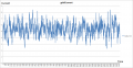
A small hydro turbine when feels mechanical jerks due change in river speed its current output starts fluctuating

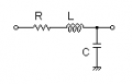
I need to make output smooth using RLC low pass filter,

Through a research paper I found natural frequency of RLC Low pass filter should be less than 3 rad/sec and that can be achived when product of L(inductance) and C (capacitance) is more than 0.12

Can someone guide me in which ratio I should select L and C and R

I have attached a diagram of output current.
 

Attachments

Papabravo

Joined Feb 24, 2006
22,082
So from a practical point of view you want the product of L and C to be greater than 0.12; one way to do that would require 1 Henry inductor and a 120,000 μF capacitor. A 1 Henry inductor that could handle 5 Amps nominal and 10 Amps peak might be difficult to purchase or construct. Large capacitors are available, but they are expensive, especially for larger voltages.

There may be other combinations that would work but it is like a seesaw, make one value smaller and the other has to get larger.
 

Thread Starter

ZeryabHassanKiani

Joined Jul 13, 2015
6
What is the current level that you need to filter?
I want to have 5 amps at output, If you share the method how you calculate that It would be great help,

I have attached circuit diagram
Peak current is 8 Amps
Peak input voltage is 550 VDC

And I want power fluctuations as low as possible

I have attached the circuit diagram, I need to know values of R L and C

If you can send me a link how calculate these it would be great help too,
 

Attachments

Thread Starter

ZeryabHassanKiani

Joined Jul 13, 2015
6
So from a practical point of view you want the product of L and C to be greater than 0.12; one way to do that would require 1 Henry inductor and a 120,000 μF capacitor. A 1 Henry inductor that could handle 5 Amps nominal and 10 Amps peak might be difficult to purchase or construct. Large capacitors are available, but they are expensive, especially for larger voltages.

There may be other combinations that would work but it is like a seesaw, make one value smaller and the other has to get larger.

I want to have 5 amps at output, If you share the method how you calculate that It would be great help,

I have attached circuit diagram
Peak current is 8 Amps
Peak input voltage is 550 VDC

And I want power fluctuations as low as possible

I have attached the circuit diagram, I need to know values of R L and C

If you can send me a link how calculate these it would be great help too,
 

Attachments

Papabravo

Joined Feb 24, 2006
22,082
L * C ≥ 0.12
Let L = 1 H
1 * C ≥ 0.12
C ≥ 0.12 Farad
0.12 F = 120,000 μF

You did not previously mention the 550 volt requirement. Finding a large capacitor with a suitable voltage rating is going to be nearly impossible. I've seen 100 V units, but that is about it. I don't see an electronic filter as the solution to your problem. The low corner frequency and the high power requirement are outside the normal realm of signal processing. Power processing is a whole different animal, one I'm not that familiar with. In fact I've never heard of filtering a current waveform, it's usually voltage. There must be a reason for that.
 
Last edited:

Thread Starter

ZeryabHassanKiani

Joined Jul 13, 2015
6
L * C ≥ 0.12
Let L = 1 H
1 * C ≥ 0.12
C ≥ 0.12 Farad
0.12 F = 120,000 μF

You did not previously mention the 550 volt requirement. Finding a large capacitor with a suitable voltage rating is going to be nearly impossible. I've seen 100 V units, but that is about it. I don't see an electronic filter as the solution to your problem.
I am not sure how this circuit will give 5 amps at output.
I am mech engineer so I donot know some basics of this circuits too
Thanks for your patience
 

Papabravo

Joined Feb 24, 2006
22,082
Whatever value you use for the resistor is going to dissipate 25*R watts and that amounts to sheer waste. I said power processing was a different animal and this might be one of the reasons. Resistors are OK in a signal path, but they are killers of efficiency when it comes to power electronics. That is why I said I don't think a signal processing filter will do you any good.
 

AnalogKid

Joined Aug 1, 2013
12,126
Agree. While the generic circuit is called RLC, that does not mean there should be three distinct components in every application. Eliminate the Resistor. Besides, the inductor will have more than enough resistance to waste some energy. To calculate the components, your statement in post #1 is correct. Since you have one equation with two unknowns, there is not one correct solution, but a set of complimentary L and C values. So the next step is to use other factors to help guide the component selection.

For best efficiency, you want the inductor to have a low resistance. However, this usually means a low inductance value, which requires a larger capacitor for the same cutoff frequency. Usually a large capacitor bank is less cost than a large inductor. But for 550 VDC you will need 1 kV capacitors. These are large and expensive. What is your budget, how many of these will be built, and what kinds of components do you have access to?

ak
 
Top