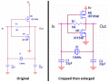
This CMOS inverter worked as an logic inverter very well. But when I tried to apply to crystal oscillator as below. It did not work at all! Could anyone here explain why ? Thanks all.
My guess would be that the gate capacitances of the two MOSFETS are preventing the circuit from oscillating. For some additional insight you might try replacing crystal X1, with its equivalent circuit. Something like this:
The feedback network for an inverting amplifier must be able to provide a phase shift of -180deg at the desired oscillation frequency. This can be realized using a 3rd-order lowpass in the classical ladder topology R-C-L-C (both C grounded). The inductance L can be realized with crystal - however the resistor R is missiung in your feedback network.
I like to use circuit below even though there can be fewer parts, in developing and testing xtal osc more info usually helpful.
The load capacitance related the impedance and drive level. Starting with an abbreviated circuit is difficult at a concept level.
Notice on a more complete schematic the resistors RF and RL on the first stage. setting into linear region, the other feedback resistor. Notice 2nd stage VL
When all the numbers work Rout will be exact. Some of the mosfets used for crystal drivers are high gain low input capacitance. Off hand some start with BF.
Finding motional parameters on a series and on a parallel mode xtal oscillator and using online calculator is usually sufficient to design good Oscillator.
I have socketed Colpitts and Pierce circuits for crystals that are very adjustable in order to narrow the scope to get the finite parameters.
When all the pieces of the puzzle are known the simulator using equivalent circuit is handy.
The datasheets for those IRF power Mosfets show a Vgs of 4V for some of them to barely conduct a very low current. They need a Vgs of 10V to fully conduct.
If you make a crystal oscillator with low capacitance little transistors then an amplifier made with IRL540 and IRL9540 Mosfets will produce a powerful output. The IRL Mosfets fully conduct with a 5V Vgs.
The feedback network for an inverting amplifier must be able to provide a phase shift of -180deg at the desired oscillation frequency. This can be realized using a 3rd-order lowpass in the classical ladder topology R-C-L-C (both C grounded). The inductance L can be realized with crystal - however the resistor R is missiung in your feedback network.
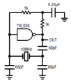
You don't often see the "R" in circuit diagrams for the Pierce oscillator using a 74HC04, but it is there as the output impedance of the gate. A physical resistor is only required for low frequency oscillators.
The requirement is to have an abrupt change of phase at the oscillation frequency. The RC gives the first not-quite-90° then the crystal or L-C network gives a change from 90° to almost 270° at the oscillation frequency
The input capacitance of the Power Mosfets you are using is much Too High for the crystal oscillator circuit.
I think the 12MHz frequency is even too high for a Cmos IC oscillator. Old LS TTL ICs were used many years ago.
I cropped and enlarged your schematic to make it easier to see the text:
try one of those 74HC chips like 74HC04, like audioguru mentioned, Vgs could be a problem ('old' mosfets for some of them they want like 7-10V to turn on). 74HC can switch on as low as like 2v.
And like others mentioned, power mostfets has additional capacitances, which could change the params. In addition, if the crystal is in the Mhz range, I'd guess try to figure out if at those frequency, it may be 'RC filtered' out that there is not enough gains to oscillate. I think the phase shift isn't 180 deg, it could be like 90-135 deg but enough to cause a positive feedback loop due to the rather high gains in the transistor.
The input capacitance of the Power Mosfets you are using is much Too High for the crystal oscillator circuit.
I think the 12MHz frequency is even too high for a Cmos IC oscillator. Old LS TTL ICs were used many years ago.
I cropped and enlarged your schematic to make it easier to see the text:
Thank you very much for your kind reply. Well, Could I ask you more question ? I would like to know what is the role of 0.25uf capacitor in the TTL version ? Thank you !
Old-fashioned TTL logic? I used it 45 years ago.
The 0.25uF capacitor prevents the two 1k DC biasing resistors from causing negative feedback which would prevent oscillation.
 Facebook
 Google
 GitHub
 Linkedin