Crystal Microphone

Thread Starter

Metalfan1185

Joined Sep 12, 2008
185
I was discussing with my father about audio circuits (hes an old radio/tube type). I wanted to build an extremely sensitive microphone amp as a kid, but I could never get it working right so i canned it. The revelation that my father gave me recently was that I was using the wrong microphone. What i needed was a "Crystal Microphone" due to its high impedance.

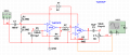
Well just how high is it? I've built a few guitar pedal pre-amps that use a pair of say 2.2M Ohm resistors to center the bias between 0 and 9v. Guitar pickups are usually high impedance, so would this microphone have enough push to utilize the input of say, a TL072? maybe a LM358?
 

Thread Starter

Metalfan1185

Joined Sep 12, 2008
185
I'm thinking something like this (attachment). The circuit is based from an older diagram that used two LM741's and a newer one based on one of my old TL072 circuits. I changed them to favor a single 9V battery. I have the power amp section in the works using a TDA1517. Ultimately it will only drive a set of earbuds with a line out option.
 

Attachments

sghioto

Joined Dec 31, 2017
8,634
The second stage doesn't look correct. From your design I think you want a 2 stage amp with each section having a gain of 10. Below is the my version of this circuit.
SG
EEE TL072 crystal mic amp.png
 

Thread Starter

Metalfan1185

Joined Sep 12, 2008
185
Thanks for your revision! I will change my circuit later and test it again.

Any idea what voltage i might expect as an output from a crystal mic? A few hundred millivolts maybe?
 

MrChips

Joined Oct 2, 2009
34,703
Any idea what voltage i might expect as an output from a crystal mic? A few hundred millivolts maybe?
Depends on how loudly you shout into the microphone.

Are you testing an electret or condenser type microphone?
Electret microphones have a built-in junction field-effect transistor (JFET) for amplification. Even though the microphone only has two leads, what you are connecting to are the DRAIN and SOURCE connections of the JFET, not the microphone itself.

The JFET needs bias voltage and load resistor to function properly.


Thread Starter

Metalfan1185

Joined Sep 12, 2008
185
I'm not sure which it is just yet. I was told to look for a crystal microphone. Round can about as round as a quarter with holes in it. about 3/8" thick, two leads. I believe there's a piezo element in there? Ill try to find a picture.
 

AnalogKid

Joined Aug 1, 2013
12,090
A crystal mic not only does not need a DC bias voltage, it doesn't want one. Stay with the input stage in post #3.

For the circuit in post #3, what is the intended gain? Compared to an electret or dynamic mic, crystal mic can put out a fairly large voltage; a gain of 100 might not be needed.

ak
 

sghioto

Joined Dec 31, 2017
8,634
A gain of 100 is probably too high for this application if the goal is to only drive headphones. Maybe drop the gain of the first stage to about 5 by changing R4 to a 470K. BTW, the TDA1517 would not be a good choice for the headphone amp if using a 9 volt battery. From the data sheet the quiescent current is typically 40 ma. Do you really need a stereo amp? I'm thinking a LM386 driving the earbuds wired in parallel.
SG
 

Thread Starter

Metalfan1185

Joined Sep 12, 2008
185
I considered the LM386 as well so that's do-able. I think I have some SMT ones, the footprint will save a lot of space as well.

As for the microphone the intended gain is really high. Think as if this circuit would exist in an almost silent environment and would pick up the sound of...well not quite a 'pin drop', but...really sensitive. If someone were talking in the same room it would potentially be EXTREMELY loud on the earbuds, but its not meant for listening to people talk, just very subtle ambient sounds.

I understand the gain is set via the feedback resistor that's connected from the output to the input. Also, I intend to build it with a short lead-length mindset with lots of grounding to prevent any kind of noise from getting in as well (most likely in a metal enclosure with some vibration dampening material).
 

Audioguru

Joined Dec 20, 2007
11,248
Crystal mics were used 55 years ago. I had one and it sounded awful. Electret mics are used today and they sound perfect.
The minimum supply for a TL072 opamp is 7V but a 9V battery quickly drops lower then the TL072 goes crazy (its output goes as high as it can) if its input swings within a few volts from ground.
 

bertus

Joined Apr 5, 2008
22,909
Hello,

Here is a desciption of a crystal microphone:

The Piezoelectric Microphone
It was long known that certain crystals, notably tourmaline, would attract light objects when strongly heated. This was the pyroelectric effect, the production of electrical polarization upon heating. While studying this effect, the brothers Pierre Curie (1859-1906) and P.-J. Curie (1855-1941) discovered the direct piezoelectric effect, or the production of electrical polarization when a crystal was strained, in 1880. In 1881 they announced the converse effect, the production of strain when an electric field was applied to a crystal. Much of the pyroelectricity previously observed was simply the piezoelectric effect due to strains caused by thermal expansion, but there is also a primary pyroelectric effect.

The application of an electrostatic field to any substance may cause mechanical strains by the phenomenon of electrostriction. These strains are proportional to the square of the applied field, and do not change if the field direction is reversed. Piezoelectricity is quite distinct; piezoelectric strains are proportional to the electric field, and reverse if the field is reversed. Piezoelectricity, where it exists, is usually much larger than electrostriction.

The description of the piezoelectric effect is made complicated by the many directional quantities and the crystal symmetries that enter. Strain is deformation per unit length, and has six components, three axial and three shear. Stress, force per unit area, also has six components. Stress and strain are related by a symmetrical matrix with, in general, 21 independent components. Electrical polarization, dipole moment per unit volume, has three components, as does the electric field. Therefore, we have 18 quantities, all depending on each other and on the orientation of the crystal. At least we can assume that the dependence is linear, and described by a certain number of coefficients.

The symmetry important here is that of the point group of the crystal, those operations leaving one point fixed. There are 32 possible point groups, each the basis of a crystal class, divided into six or seven crystal systems. Crystals that do not have a centre of symmetry may exhibit piezoelectricity; those with a centre of symmetry cannot, by Neumann's theorem, which states that any property of a crystal must have at least the symmetry of the crystal. Such crystals are called hemihedral. Their axes are essentially one-sided, and opposite directions on them are not equivalent. This is required if the piezoelectric strain is to be proportional to the electric field, and reverse with it. Of the 32 crystal classes, 20 may be piezoelectric. There are, in general 18 coefficients connecting the electric field to the strain in the direct effect, or the polarization to the strain in the converse effect.

If X is a stress, in dyne/cm2, and x is a strain, dimensionless, then the relation between them is of the form X = kx, where k has the dimensions of stress, and is called an elastic modulus. The inverse relation is x = sX, where s = 1/k is called a compliance, with dimensions cm2/dyne. This is really a matrix relation, and the matrix s is the inverse of the matrix k, not a simple reciprocal, though often the actual relations are simple. Analogously, the direct piezoelectric effect can be expressed by P = ex, where x is strain, P the polarization in esu/cm2, and e is a piezoelectric constant with the dimensions of polarization. The converse effect can be expressed by x = dE, where x is the strain, E the electric field in statvolt/cm or erg/esu, and d is a piezoelectric constant, with dimensions of inverse field. The polarization and the electric field are also related by P = ηE, where η is the electric susceptibility. Again, it must be emphasized that these are all tensor relations generally involving many coefficients, and a constant spontaneous polarization Po may also be involved. In that case, the P above is the change due to E.

When the Curies made their initial studies, which included discovering the piezoelectricity of quartz, which has been very important, they found that Rochelle salt, or Sel de Seignette (a pharmacist in La Rochelle who isolated and discovered the medical properties of the salt in 1672), had an extremely large piezoelectric effect. Rochelle salt was used extensively in microphones, and is of considerable interest besides, so the discussion here will focus on it. However, it is typical of all such materials. Rochelle salt is sodium-potassium tartrate tetrahydrate, NaKC4H4O6·4H2O, which easily forms large orthorhombic crystals. Above 55°C, it begins to form separate Na and K tartrates dissolve in the water of crystallization, and disintegrates irreversibly. To preserve the crystal, it should not be heated above 45°C. Its large piezoelectric effect occurs only between -18°C and +24°C, called the lower and upper Curie Points of the substance. Between these temperatures, it is an electrostatic analogue of a ferromagnetic material, called a ferroelectric, with a large spontaneous polarization. Like ferromagnetic materials, it is divided into domains of constant spontaneous polarization, but the domains are quite large, even centimetres in size. The domains are not obvious to the eye. Its crystals are enantiomorphic, like quartz, but only right-handed crystals occur in most cases.

An X-cut crystal plate of Rochelle salt is shown at the right. The x,y,z axes correspond to the crystallographic axes a, b,c. An X-cut plate has the normal to its broad surface parallel to the x-axis. There are only three piezoelectric coefficients for Rochelle salt, which relate the three shear strains to the three components of the electric field. The shear stress Yz is a force per unit area in the z-direction on a surface whose normal is parallel tot the z-axis. For equilibrium, it must be equal to Zy. The opposite faces have the same forces acting, but in the reverse direction. This shear stress gives rise to an electric polarization in the direction shown, with d14 as the coefficient. The other nonzero coefficients are d25 and d36, relating to zx and xy shears, respectively. The three coefficients are different in value, but d14 is the largest. For Rochelle salt, d14 is about 2.6 x 10⁻⁴ cm/statvolt, or 1/d = 3850 statvolt/cm (the electric field for unit strain). For a strain of 10-4, an electric field of about 115.5 V/cm is required. The exact value of d depends on the temperature and the circumstances of the crystal, but this gives an idea of its magnitude.

A "45° X-cut rod" is an X-cut with the lateral sides making equal angles with the z and y axes. The shear strain yz is 2ΔL/L, if L is the length of the rod, and ΔL is the change in length. The formula at the right in the diagram for the converse effect serves to find the change in length for any applied field. Of course, the strain and stress are related by the elastic constants of Rochelle salt, but we will not go into that here.

Ammonium dihydrogen phosphate or ADP, NH4H2PO4, as well as the potassium salt potassium dihydrogen phosphate or KDP, are also strongly piezoelectric, resembling Rochelle salt quite closely. The Curie temperature of ADP is 147.9°C, it has no water of hydration, and is quite stable, so it makes more durable devices. The symmetry is about the same, but a little higher, so that d14 = d25. Ceramics like barium titanate, BaTiO3, which are ferrielectrics (two lattices oppositely polarized spontaneously; the observed polarization is the difference), also are strongly piezoelectric. If a microphone is described as "crystal," it usually contains ADP; if it is called "ceramic," barium titanate is the active element. Any piezoelectric device is reversible; if a voltage is applied to a piezoelectric microphone, it will emit sound. It is also strictly a passive electroacoustic transducer, and the output power cannot exceed the acoustic input power.

Rochelle salt first became more than a curiosity around 1917, when it was applied by Langevin to ultrasonic acoustic transducers, or hydrophones, for the detection of submarines. Not only could strong signals be created in water by the converse piezoelectric effect, but the same crystals could be used to detect the reflected waves. This was, in fact, the origin of the important field of ultrasonics, which used acoustic waves of greater frequency than 20 kHz, which were inaudible but very useful.

The impedance mismatch between air and a diaphragm is much greater than the mismatch between water and a crystal hydrophone, so microphones are much more difficult to devise. The first microphones had a 45° X-cut bar, 1-2 cm long, 0.4-1 cm wide and 0.1 to 0.2 cm thick, cemented between a diaphragm and a backing plate. A much more sensitive arrangement was a "bimorph" of two cemented X-cut plates with one thin electrode between them. They could be arranged to bend or twist, and could be operated from a diaphragm through mechanical leverage. A typical inexpensive modern ceramic microphone responds from 30 Hz to 15 kHz, with a sensitivity of -60 dB (1 μV/μbar) and an advertised internal impedance of 8kΩ at an unspecified frequency (Kobitone LM037). The capacitance measures 786 pF, which gives a capacitive reactance of 20.2 kΩ at 1 kHz. Piezoelectric microphones give low output at a moderate internal impedance, and must always be used with amplification.

Piezoelectric transducers were used as analog phonograph pickups, giving a much higher output than dynamic pickups. As driven elements, piezoelectric devices are used as telephone receivers, acoustic transducers and record cutters. They are used for small loudspeakers, although dynamic loudspeakers give much better results. In 1925, G. W. Pierce invented the acoustic interferometer, which uses an X-cut plate and a parallel reflector to measure the speed of sound with great accuracy. He devised an oscillator that was very sensitive to the reaction of the air on the crystal. W. G. Cady developed the quartz crystal resonator at about the same time, which has had widespread application as a frequency-control device.

This comes from this page:
http://mysite.du.edu/~jcalvert/tech/microph.htm

Bertus
 

Thread Starter

Metalfan1185

Joined Sep 12, 2008
185
Sorry it took so long to get back. For some reason the site wouldnt let me log in on my PC. Thank you for that read there's a lot of good stuff in there. I like reading about history in electronics (Tesla is my favorite!). Anyways, i think ill play with a few different kinds of mics and see what i can get out of each one. Still waiting to find a cheap(er) Xtal mic.

Cheers!
 

Thread Starter

Metalfan1185

Joined Sep 12, 2008
185
I will, thanks!

I remember a particularly good documentary on it. It was called "The men who built America" Its a multiple part series over a variety of topics in history, but one particular section explains a lot about Tesla and Edison.
 

MisterBill2

Joined Jan 23, 2018
27,336
Crystal mics were used 55 years ago. I had one and it sounded awful. Electret mics are used today and they sound perfect.
The minimum supply for a TL072 opamp is 7V but a 9V battery quickly drops lower then the TL072 goes crazy (its output goes as high as it can) if its input swings within a few volts from ground.
SOME crystal microphones sound good, but they are such high impedance devices that a longer cable will very much reduce the high frequency response. AND there are all different quality levels available, as the microphones varied from $2 units up to a whole lot more. And then there are ceramic microphones, similar to crystal ones but more robust elements not moisture or heat sensitive. For loud sounds up close one of my microphones put out almost 100mV. But for soft sounds in a quiet area you will want a lot more gain, perhaps 1000 in the two stages. The reason to split the gain between stages is that as the gain is boosted the frequency response can drop off, (gain-bandwidth product), so at somewhat lower gains the response is better. But you may also discover that there is too much high frequency gain, since the TL072 is good for some fairly high frequencies. You may need to ecperiment a bit in that area.
 
Top