 Facebook
 Google
 GitHub
 Linkedin
Hello,
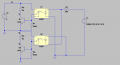
I am trying to detect each zero crossing of mains A.C. voltage.
Do i need to use two opto-couplers like what is shown in the circuit or
is there a device that works for both directions. v1 and v3 shown in the
circuit would go to a micro-controller that fires the triac through a diac
which is not shown in the schematic.
Thanks in advance
Joe
Attachments
-
 14.9 KB Views: 18


