 Facebook
 Google
 GitHub
 Linkedin
Hi all, I'm a third year Computer Science student & I've decided for my third year project I want to do something with pulse oximetry. I'm trying to build a pulse sensor and then do something with the results such as build graphs and analyse real time. Although I'm more concerned about the programming of software I'm also interested in trying to build a device like this.
I've got no background in electronics but thought it might be fun.
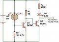
I'd been following the schematic which is attached and I've been able to ensure it works (kind of) by checking the serial monitor from my Arduino interface. The problem is, when I try to place my finger between the LED and LDR, the LDR is not absorbing any light and I'm unsure why.
Here is the tutorial I've been following:
http://www.instructables.com/id/Homebrew-Arduino-Pulse-Monitor-Visualize-Your-Hear/?ALLSTEPS
I've got no background in electronics but thought it might be fun.
I'd been following the schematic which is attached and I've been able to ensure it works (kind of) by checking the serial monitor from my Arduino interface. The problem is, when I try to place my finger between the LED and LDR, the LDR is not absorbing any light and I'm unsure why.
Here is the tutorial I've been following:
http://www.instructables.com/id/Homebrew-Arduino-Pulse-Monitor-Visualize-Your-Hear/?ALLSTEPS
Attachments
-
 25.7 KB Views: 13
") I got a little deterred from the MAKE guide as I seen some of the comments saying that the circuit does not work, any thoughts?
I got a little deterred from the MAKE guide as I seen some of the comments saying that the circuit does not work, any thoughts?


