signal can be inverted using another opamp or comparator or a transistor..
step 1 accomplished - you got a working oscillator.
step 2 duplicate it to get second oscillator that runs at higher frequency
step 3 buffer or invert signal as needed
step 4 combine signals...
step 5 ...
...
step 10 see if things could be optimized / simplified
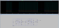
I tried and draw a schematic including 2 oscillators. But in the second oscillator, capacitor c2 is charging and discharging when capacitor c1 is discharging. I want to make it opposite. I want to make cap c2 charge and discharge when c1 is charging..
I have attached my schematic below.
I want yo design a circuit where when a capacitor is charging and above a given threshold, the output will be pulse train and when it is below reference voltage tye output will be low. I have attached a handwritten expected waveform below. I tried to make it using ltspice which I have attached. But my output comes out to be opposite of what I expected.
The schematic includes 2 oscillators. In the second oscillator, capacitor c2 is charging and discharging when capacitor c1 is discharging. I want to make it opposite. I want to make cap c2 charge and discharge when c1 is charging..
Have you thought of using a comparator in place of Q1 ? You could even connect one input of this comparator to the top of C1 (triangular wave form.) and connect the other input to a variable voltage which would let you adjust the duty cycle of the square wave on it's output. This would allow you to control how many pulses were in each group.
 Facebook
 Google
 GitHub
 Linkedin