Creating a circuit from the waveform.

Thread Starter

moonlystar1111

Joined Feb 1, 2024
65
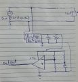
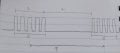
Can anyone please tell how to create a comparator circuit which gives output waveform as attached. The curvuit should be made using comparator, op amp, capacitor, resistor etc.
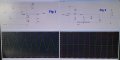
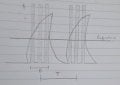
1. It is when charge at capacitor is greater than the reference voltage.
2. It is when charge at capacitor is lessor than the reference voltage
 

Attachments

ericgibbs

Joined Jan 29, 2010
19,177
Hi 1111,
You could consider a 555 timer for the square wave source and Gate its output using a LM393 comparator.
What is the frequency of the pulse train?
E
 

Thread Starter

moonlystar1111

Joined Feb 1, 2024
65
Hi 1111,
You could consider a 555 timer for the square wave source and Gate its output using a LM393 comparator.
What is the frequency of the pulse train?
E
The pulse train has frequency of 3 KHz. Initially it is connected with 110 v 60 hz supply, which is then converted to dc voltage of 5 v. This 5 v is vcc to comparator.
 

LesJones

Joined Jan 8, 2017
4,238
With the restrictions on the method it sounds like a homework question. Is this the case or is there another reason for the restrictions ?

Les.
 

panic mode

Joined Oct 10, 2011
2,914
regardless if this is a homework or not - show your effort.
circuits are built piecemeal and then combined.

from your post i do not see how the circuit is supposed to work because you did not state basics:
it clearly has an output but there is no indication if there is an input. is this supposed to continuously output series of pulses in bursts from the moment it is turned on? that would be operation without input.

and if it is using an input, is the output supposed to run the mentioned waveform exactly ONCE for each input trigger?
what is input is triggered multiple times while one series of pulses is still being generated?

what is the timing? what are the values for T, D and voltage levels? why this need to be done as analog circuit and not digital? because with analog, getting precise timing cab be difficult. using precision clock and counters, one can get MUCH more accurate results.
 

Thread Starter

moonlystar1111

Joined Feb 1, 2024
65
regardless if this is a homework or not - show your effort.
circuits are built piecemeal and then combined.

from your post i do not see how the circuit is supposed to work because you did not state basics:
it clearly has an output but there is no indication if there is an input. is this supposed to continuously output series of pulses in bursts from the moment it is turned on? that would be operation without input.

and if it is using an input, is the output supposed to run the mentioned waveform exactly ONCE for each input trigger?
what is input is triggered multiple times while one series of pulses is still being generated?

what is the timing? what are the values for T, D and voltage levels? why this need to be done as analog circuit and not digital? because with analog, getting precise timing cab be difficult. using precision clock and counters, one can get MUCH more accurate results.
Yes this can be digital, but I was working on analog circuit Designing that is why I need to only simulate it that way.
Value of D = 1 msec
Value of T= 60 sec
Voltage level is 120 v 60 hz sinusoidal, which is then rectified and regulated to 20 v.
The somehow expected circuit is shown below.
 

Attachments

LesJones

Joined Jan 8, 2017
4,238
You drawing in post #8 has problems. If your zener diode voltage ls than about 170 volts then it will be destroyed as you do not have a current limiting resistor. If the zener diode voltage is as greater than 170 volts then you will be supplying the opamp / comparitor with 170 volts. I do not know of one that works with such a high voltage.

Les.
 

Thread Starter

moonlystar1111

Joined Feb 1, 2024
65
You drawing in post #8 has problems. If your zener diode voltage ls than about 170 volts then it will be destroyed as you do not have a current limiting resistor. If the zener diode voltage is as greater than 170 volts then you will be supplying the opamp / comparitor with 170 volts. I do not know of one that works with such a high voltage.

Les.
No.. the zener will regulate the voltage to 2 volts.
 

panic mode

Joined Oct 10, 2011
2,914
i sure could... but how are you going to learn if you don't try it yourself?
you re supposed to try and if/when you get stuck, ask for pointers and explanations. then rinse and repeat stage by stage.
normally comparators have open collector output, this is intentional and convenient. one can connect outputs of two or more comparators together to create so called wired gate. so start by making two suitable oscillators like i did with NAND, tie their outputs together, build the circuit on breadboard or at least simulate it (LTSpice is great and free). then we talk...
 
Last edited:

Thread Starter

moonlystar1111

Joined Feb 1, 2024
65
i sure could... but how are you going to learn if you don't try it yourself?
you re supposed to try and if/when you get stuck, ask for pointers and explanations. then rinse and repeat stage by stage.
normally comparators have open collector output, this is intentional and convenient. one can connect outputs of two or more comparators together to create so called wired gate. so start by making two suitable oscillators like i did with NAND, tie their outputs together, build the circuit on breadboard or at least simulate it (LTSpice is great and free). then we talk...
I tried to make it using single astable oscillator. But the output is high when capacitor starts charging and low when it starts discharging. I want output to be high when charge at capacitor crosses a reference threshold and this pulsating output have a frequency of oscillation. After this it will stop oscillating and gives low output upon discharging of capacitor. ( fig 1)

Another circuit I tried which gives high output when capacitor charge is above threshold but I want pulsating output with some frequency. (Fig 2)

The required graph is manually drawn below.
 

Attachments

panic mode

Joined Oct 10, 2011
2,914
signal can be inverted using another opamp or comparator or a transistor..

step 1 accomplished - you got a working oscillator.
step 2 duplicate it to get second oscillator that runs at higher frequency
step 3 buffer or invert signal as needed
step 4 combine signals...
step 5 ...
...
step 10 see if things could be optimized / simplified
 
Top