 Facebook
 Google
 GitHub
 Linkedin
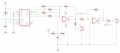
I have a circuit in which I use a 74HCT193 counter and create a bipolar stair step signal from its outputs. When the signal at the Count-Up input has 50% duty cycle, the output is as expected. When the duty cycle increases, the output gets weird. What could be causing this? The maximum input frequency I give it is around 18Hz, so I'm nowhere near the frequency/time limits of the part.
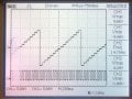
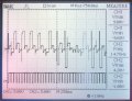
The first attachment shows the counter and stair step part of the circuit. The input to the count-up input (CPU) comes from a rotary switch which is currently set to the output of a NAND gate. The second attachment shows the step-up output when the output of the NAND gate is about 50% duty cycle. The third attachment shows the output when the duty cycle is around 80%. The last attachment is a smaller time scale so you can see more how the output compares to the input. In that image you can see that the output changes on high-low transitions as well as low-high, which shouldn't happen. It should only change on low-high.
I verified the circuit with a 74LS193 on my breadboard and the output was as expected for any duty cycle at a similar frequency (15Hz).
The whole circuit is a modulation source I made for a modular synthesizer. The input to the counter is ultimately derived from oscillators, via logic gates and analog comparators, and the oscillator I'm currently using has square and triangle outputs. When it's set to square, everything is fine. The triangle output gives a higher duty cycle at the output of the NAND gate, which does weird things to the output of the counter.
Any ideas what's going on?
Attachments
-
 125.8 KB Views: 16
 -
 204.1 KB Views: 13
 -
 248.3 KB Views: 13
 -
 217.6 KB Views: 13


