Count 1's and 0's of a bit stream

Thread Starter

Tera-Scale

Joined Jan 1, 2011
164
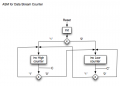
I need to implement a system for counting the number of one's and 0's in a bit stream. These will be made of two 4-bit counters one for the 1's and other for 0's. At each rising edge, the system checks the logic of bit stream and increments the counters according.

My simple ASM is attached. Is this the only way to implement this system using an ASM ? or is it possible to go deeper ?

I also need to convert the asm to a one flipflop per state. Will this result in two ring counters? If this is the case then it would need to load the first flip flop initially. The rest would be a 2-to-1 demux to select the clock path according to the input data stream. Any suggestions would be appreciated.
 

Attachments

kubeek

Joined Sep 20, 2005
5,796
I´m not sure I understand what you mean, what will be the final implementation? A diagram of a state machine?
If this is going to any practical implementation, then gating clocks is generally a big no-no, you should allways gate the data.
 

Thread Starter

Tera-Scale

Joined Jan 1, 2011
164
I´m not sure I understand what you mean, what will be the final implementation? A diagram of a state machine?
If this is going to any practical implementation, then gating clocks is generally a big no-no, you should allways gate the data.
This would be implemented on an fpga, it is sort of an exercise. The clock and data would be generated via button switches..
 

WBahn

Joined Mar 31, 2012
32,989
You show an output coming from the counter and then going into the decision box for x. That makes no sense. How is the output of the counter affecting anything.

The "ena" is referring to the enable input of the counter.

This can be done with two counters and an inverter.

You definitely don't want to gate clocks in an FPGA. Also, if your clock is going to be generated by a switch, be sure to debounce the switch before it gets to the FPGA.
 

Brownout

Joined Jan 10, 2012
2,390
Here is pseudo code

Rich (BB code):
always @(posedge clk) begin // positive clock edge detection
if(reset)
//reset counters
else begin
if(data_valid) //input data is valid
if(data == '1')
1's_counter <= 1's_counter + 1;
else
0's_counter <= 0's_counter + 1;
end
end
 

WBahn

Joined Mar 31, 2012
32,989
Here is pseudo code

Rich (BB code):
always @(posedge clk) begin // positive clock edge detection
if(reset)
//reset counters
else begin
if(data_valid) //input data is valid
if(data == '1')
1's_counter <= 1's_counter + 1;
else
0's_counter <= 0's_counter + 1;
end
end
Perhaps the OP should be given the opportunity to come up with a first shot at a solution after taking the feedback provided thus far before just giving them a major piece. This appears to be an assignment or academic exercise and thus should probably be in the Homework Help forum where this would be more apparent.
 

WBahn

Joined Mar 31, 2012
32,989
I have no idea why a FPGA should be beneficiary over a CPLD for that.
It doesn't matter if an FPGA is better than a CPLD for this particular task. Are you familiar with the concept of a "Hello World" program? When someone is being taught a new programming language the classic first program is something that just does a very simple thing so that the student can focus on learning the mechanics of getting anything to work in that language. So it would not be very beneficial to tell them that some other language is a better choice if all they want to do is print a fixed string of text to the screen.
 

Brownout

Joined Jan 10, 2012
2,390
Perhaps the OP should be given the opportunity to come up with a first shot at a solution after taking the feedback provided thus far before just giving them a major piece. This appears to be an assignment or academic exercise and thus should probably be in the Homework Help forum where this would be more apparent.
Which is why I offered pseudo code. This code will not build or run. It's intended as a guide only.
 

Thread Starter

Tera-Scale

Joined Jan 1, 2011
164
Here is pseudo code

Rich (BB code):
always @(posedge clk) begin // positive clock edge detection
if(reset)
//reset counters
else begin
if(data_valid) //input data is valid
if(data == '1')
1's_counter <= 1's_counter + 1;
else
0's_counter <= 0's_counter + 1;
end
end
Thanks for your guidance Brownout, I will code that in VHDL.

One more question. I just started VHDL and till now I wrote a description for a JK flip flop, and also of a ripple counter. Looking at your pseudo code, it seems that I would not be needing a description for any memory element. I think that quartus would do all the work. Attached is a schematic of which I think should be the result. Each counter works separetely but it still needs some tweaking.
 

Attachments

Last edited:

Brownout

Joined Jan 10, 2012
2,390
You're need to declare the counters and other signals. Once you've writting all the code to handle counting, the systhesis tool will instantiate any flip-flops needed, assuming you did it right.
 

WBahn

Joined Mar 31, 2012
32,989
Thanks for your guidance WBahn, I will code that in VHDL.

One more question. I just started VHDL and till now I wrote a description for a JK flip flop, and also of a ripple counter. Looking at your pseudo code, it seems that I would not be needing a description for any memory element. I think that quartus would do all the work. Attached is a schematic of which I think should be the result. Each counter works separetely but it still needs some tweaking.
You should thank Brownout more than me (at least for the pseudocode).

HDL code that closely resembled the above pseudocode is called "behavoral" code and the underlying structures are inferred from the behavior. In particular, the fact that things happen only on a clock edge implies a clocked memory element. Then the fact that things are not fully specified as to what should happen for all possible combinations of the inputs causes latches to be inferred, where necessary, to effect the behavior of "nothing" happening.

The alternative is to write code in a "structural" fashion in which you are just "wiring up" lower level modules. Coding styles vary greatly. Personally, I like to use behavoral code only for the lowest level blocks and to then tie the blocks together structurally to form a system. But that preference is highly influenced by the fact that I designed ASICs with millions of transistors using a schematic-based approach and so became very adept and comfortable with thinking in terms of hierarchies and levels of abstraction in which the minute analog behavior was dealt with, whenever possible, at the lowest, smallest circuit level.
 
Top