Could someone explain how to calculate LM723 output voltage?

hp1729

Joined Nov 23, 2015
2,304
Design 817 LM723 full range.PNG View attachment 110783
Datasheet: http://www.ti.com/lit/ds/symlink/lm723.pdf

I'm having a hard time to figure out how to set the output voltage. I'm even confused where to put the divider resistors. Sometimes it's between pin 6 and ground. other times it is between current sense and ground. I was also wondering what the value of VREF is? for example if i want 12v out, what/where to i put the resistors?

Or if i want an adjustable 2.8 - 12v, where to put potentiometer etc.

Cheers!!
It may be a late entry but yes the LM723 can be made to go from around 3V to around 12 V. The two circuits can be combined. Attached is a simplified example.
 
Last edited:

#12

Joined Nov 30, 2010
18,224
It may be a late entry but yes the LM723 can be made to go from around 3V to around 12 V.
The LM723 can go from very little to umpteen volts, or be taught to act as a thermostat.
It's a voltage reference and an op-amp with a couple of output limiting transistors.
Playground for the nerd class.
I have one that doesn't use a 723, just the ideas learned from the 723. Different voltage reference, different op-amp, but it goes from zero to 1000V
http://forum.allaboutcircuits.com/attachments/723float-png.72328/

There I have a few that actually use the LM723
Check my blogs:
http://forum.allaboutcircuits.com/attachments/lm723floatingregulator-png.72329/
http://forum.allaboutcircuits.com/attachments/723-thermostat-png.72348/
 

Attachments

Thread Starter

psrkallez06

Joined Dec 17, 2015
68
No, but I'll make one just for you.
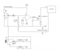
Here's the basic shape of it.
A differential amp creates a negative voltage proportional to the current through the sense resistor. Then you make a negative voltage with a pot and compare that to the amplified sense voltage. Then, that amplifier turns on a dumping transistor as much as it takes to defeat the LM723. You might send the dump line back to the zener input if that suits your purposes.
This is my first try at this, so there might be a better way.

There is a simpler way if you place the sense resistor between the load and ground. That just requires one op-amp, but you either lose the accuracy of the voltage setting or you connect your voltage reference for the LM723 at the point before the sense resistor. I could work that out if I tried.
Thank you very much for your time! Gonna try and simulate that!!
 

#12

Joined Nov 30, 2010
18,224
If I was going to mess about with that, I'd use a tiny Rsense and put more gain on the differential amp to make the adjustability smoother. That's, "more resistance in the negative feedback resistor".

Of course, there is a trade-off to decide, based on how much negative voltage you want to provide for the voltage adjuster on the last op-amp. If you only have 5 volts for your negative reference, that's how you scale the gain in the differential amp.
 

ian field

Joined Oct 27, 2012
6,536
The LM723 can go from very little to umpteen volts,
/
In the past; I've seen an appnote example for a floating 723 that can regulate an output at a lot more than its own voltage rating.

There is a 3 terminal regulator specifically designed to work like that - but I've always considered it a rather dubious practice.
 

#12

Joined Nov 30, 2010
18,224
There is a 3 terminal regulator specifically designed to work like that - but I've always considered it a rather dubious practice.
It seems to make sense when you realize the isolated transformer winding for the LM723 regulator rides up on the output voltage, so it isn't energized until the regulator has control of the circuit. Just...I can't remember seeing the example of a 3 terminal regulator doing high voltages. Got a link? A part number? An appnote?
 

#12

Joined Nov 30, 2010
18,224
I just fiddled around with a current limit when Rsense is between the load and ground. You just ground the LM723 above the sense resistor to keep the output voltage function from being altered by the voltage across Rsense, then use an inverting amp to amplify the voltage across Rsense and send that to a comparator with an adjustable negative voltage set point much like the previous design. This time you can't use a differential configuration, you just use an inverting amplifier to make a signal for the comparator. Both designs need a negative supply voltage to run the current controlling op-amps and to set a decision voltage with a pot.

The reason I didn't do this in 40 years is that the fold-back circuit in the LM723 has always been good enough for commercial designs sold merely as a power supply. What we're talking about here is a professional bench supply with deadly accurate and repeatable constant current control. Both designs use 2 op-amps to go into constant current mode, so it seems much simpler to use the first design rather than mucking about with a false ground above the Rsense voltage.
 

ian field

Joined Oct 27, 2012
6,536
It seems to make sense when you realize the isolated transformer winding for the LM723 regulator rides up on the output voltage, so it isn't energized until the regulator has control of the circuit. Just...I can't remember seeing the example of a 3 terminal regulator doing high voltages. Got a link? A part number? An appnote?
TL783 - 3rd hit with the search term; "high voltage 3 terminal regulator".
 

Thread Starter

psrkallez06

Joined Dec 17, 2015
68
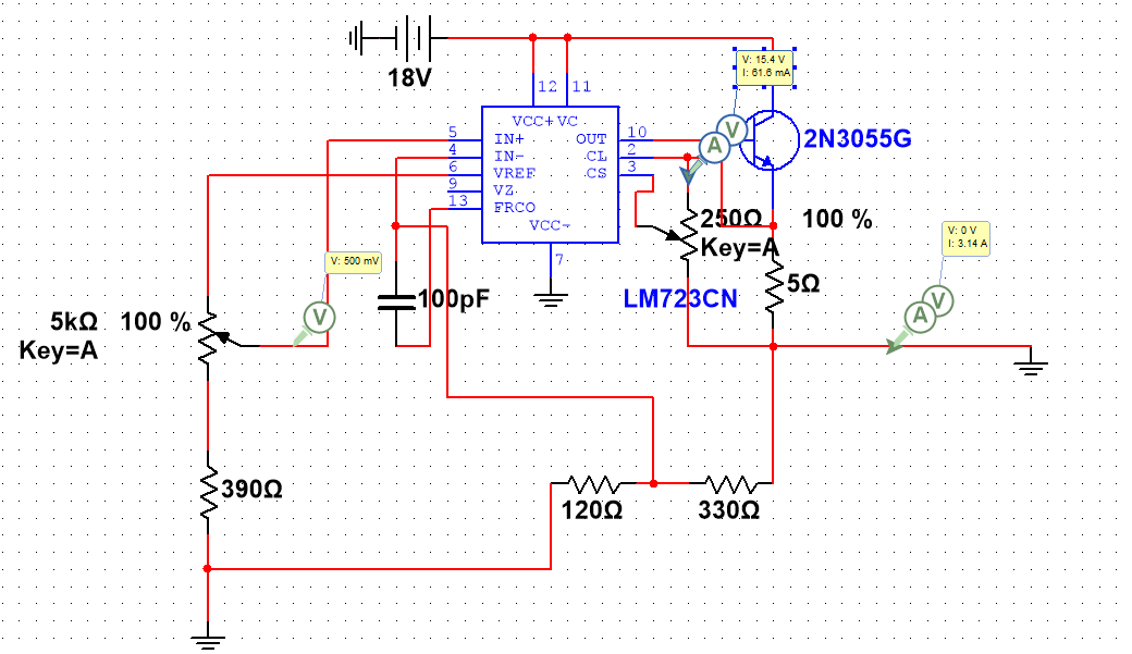
Hello again, So i got me ten turn 250 ohm pot for a crude current limit, the problem is that the pot is getting pretty hot


When 3 amps of current flows, over 60 mA flows through the pot, does anyone know how i can lower the current going through the pot? Or should i just get a better pot? Got a cheap one from ebay. Cheers.
 

crutschow

Joined Mar 14, 2008
38,627
Over what range do you want to vary the current limit?
Your circuit makes little sense.
How can you get 3A from that circuit? 60mA (how did you come up with that value?) through the pot means you would be putting nearly 3A through the 5Ω emitter resistor.
That would drop 15V across the resistor while dissipating 45W in the resistor, obviously not what you want.
 

Thread Starter

psrkallez06

Joined Dec 17, 2015
68
Over what range do you want to vary the current limit?
Your circuit makes little sense.
How can you get 3A from that circuit? 60mA (how did you come up with that value?) through the pot means you would be putting nearly 3A through the 5Ω emitter resistor.
That would drop 15V across the resistor while dissipating 45W in the resistor, obviously not what you want.
Obviously I've got a lot to learn.. From PIN 2 down through the pot, there you can see 61 mA. If i got to choose the range i would think that 100 mA or 300 mA - 3A would be good, I'm new with the LM723, right now I'm just playing around with some random stuff. The 5Ω emitter resistor i used to limit the current to 3A. Is there another way to do it? Thanks again.
 

crutschow

Joined Mar 14, 2008
38,627
The value of the emitter resistor determines the minimum current limit adjustment.
Thus for 300mA the value would be 0..65 / 0.3 = 2.1Ω.
Say we used 2Ω which would give a minimum current limit of .65 / 2 = 325mA.
Then if you adjusted the pot to give 3A, there would be 6V dropped across, and 18W dissipated by the 2Ω resistor.
That's a lot of voltage drop and a lot of dissipation, so you might want to consider reducing the current adjustment range to make the maximum voltage and dissipation more manageable.

For example, reducing the resistor to 1Ω would give a minimum current limit of 650mA with a voltage drop of 3V and a resistor dissipation of 9W @ 3A.
 
Last edited:

Thread Starter

psrkallez06

Joined Dec 17, 2015
68
Thanks for your answer, So i did reduce the resistor to 1Ω which is perfect, i got a 10W resistor so i should be good. I'm gonna stress test it for a bit to be sure that it doesn't burn up, if it does I'll add two 10W in parallel.

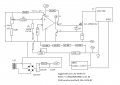
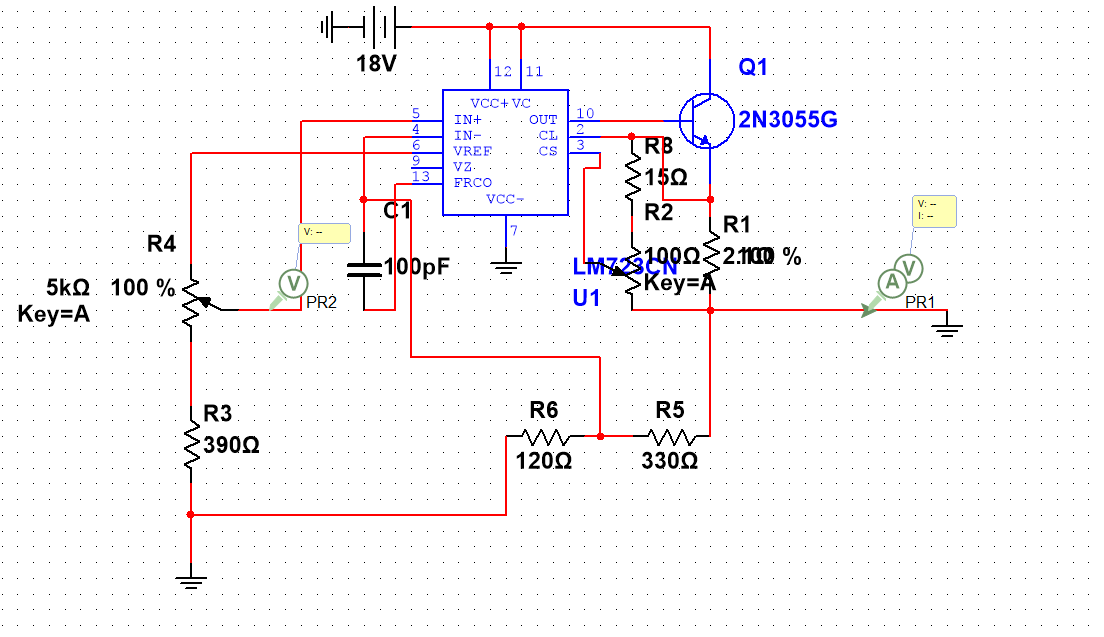
So now i have another problem, I'm sure that you already answered this in the above posts but I'm still confused about the voltage adjustment, Right now I'm using a 18V battery for the Vin (gonna change that later to a transformer with a bridge rectifier etc).I'm using a 10K ten turn pot for the voltage adjustment, but many % of the pot is useless, my minimum voltage is also around 3.5V, i would prefer 2.8v - 18v and be able to use most of the pot. What is the value for the resistors i need to change?


ignore the ratsnest to the right since the current limiting part is solved thanks to you, Do i need to change R3/R5 or R6? Or all of them? Cheers!
 
Top