 Facebook
 Google
 GitHub
 Linkedin
Hey guys,
I'm new to the forum as a user and a newbie on electronics and circuits.
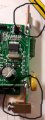
So, I am checking out the PCB of a DIN rail power meter to better understand its circuit design. On "conn.jpg" you can check the copper conector - the IN is the input for the phase (then the energy is measured) and the phase gets out of the circuit by the OUT terminal.
My questions are as follows:
1) What is the name of this kind of copper input/connector? I have seen rubber ones with screws, but I have not been able to find this one specifically.
2) In "conn.jpg" you can check that the copper plate is the same for "IN" and "OUT". Are they connected or is there some kind of isolation between them? I have seen a via on the PCB connected to the "OUT" so I'm unsure if IN and OUT are connected directly by the copper as I've never seen this kind of screwed input/output.
Thank you very much in advance!
I'm new to the forum as a user and a newbie on electronics and circuits.
So, I am checking out the PCB of a DIN rail power meter to better understand its circuit design. On "conn.jpg" you can check the copper conector - the IN is the input for the phase (then the energy is measured) and the phase gets out of the circuit by the OUT terminal.
My questions are as follows:
1) What is the name of this kind of copper input/connector? I have seen rubber ones with screws, but I have not been able to find this one specifically.
2) In "conn.jpg" you can check that the copper plate is the same for "IN" and "OUT". Are they connected or is there some kind of isolation between them? I have seen a via on the PCB connected to the "OUT" so I'm unsure if IN and OUT are connected directly by the copper as I've never seen this kind of screwed input/output.
Thank you very much in advance!
Attachments
-
 130.5 KB Views: 25
 -
 57.1 KB Views: 24
 -
 103.9 KB Views: 23
")


