Converting dual rail circuit to single supply

Thread Starter

Stephen Flynn

Joined Sep 29, 2015
43

Hi, I'm trying to build a small portable, battery/walwart powered guitar amplifier. I have a power amp AN7523 chip that outputs 5w from an 12v supply on a breadboard, is a single supply chip a with a max input voltage of 14v. Been trying various preamp circuits, with some success. But so far, yet to hear that magic sound. All my attempts have worked but a bit dull, or overly bright when certain strings on the guitar are strummed.
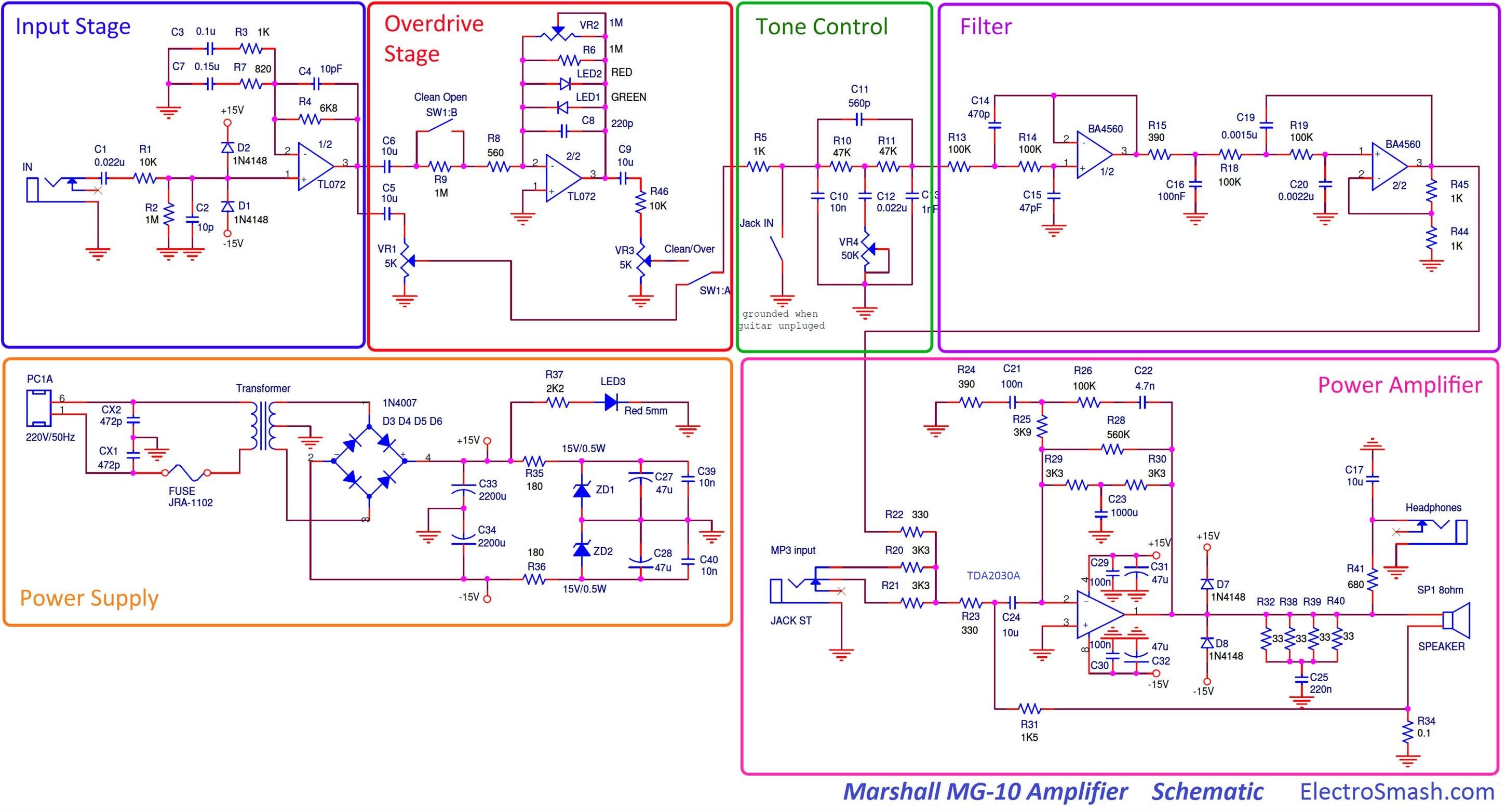
I'm trying to modify this circuit for a Marshall Mg10 amp that runs on +-15v dual rail supply. I am trying to get the circuit to function on single 12v supply to fit my power amp. I'm especially interested in this circuit because it uses a sallen key filter at the end of the preamp. I'm keen to explore what effect that will have on a preamp.
Using 2 caps and 2 identical value resitors I created 12v - 6v (vdd/2) - Virtual gnd supply on my breadboard and arrange so that one side of my bread board has 6v/gnd, and the other has 12v/gnd rails.

I have breadboarded the first 2 stages , and tried feeding a Vdd/2 voltage supply to the non-inverting inputs of both stages, through a resistor. I just get squealing noises and oscillations, and the output voltage seems to pulse the power amp.

I checked the voltage from the output of the first stage, it seems stable and measured at roughly the same voltage as the vdd/2. The second stage seems to have aglitch, but I don't where.

I have also tried this as inverting stages...I get some signal, but not very stable as well..
Can anyone give some pointers on the types of calculations that need to happen here?? I'm pretty clueless and come to a deaend. and can't directly find much information about "converting" circuits..it must happen, but obviously not very often :
 
Last edited:

Bordodynov

Joined May 20, 2015
3,177
I advise you to put the capacitors of the filter to the resistive divider.
One oxide 100 μF and ceramic 0.1 μF or more.Condensers must be included between the virtual and real lands.
 

Thread Starter

Stephen Flynn

Joined Sep 29, 2015
43
I advise you to put the capacitors of the filter to the resistive divider.
One oxide 100 μF and ceramic 0.1 μF or more.Condensers must be included between the virtual and real lands.
yes, OK thanks, I have not attempted the filters yet, I can't get the first 2 stages ( input and gain) working.
 

Thread Starter

Stephen Flynn

Joined Sep 29, 2015
43
Messing with the clean channel only - I am able to get signal that sounded pretty good, although unstable, by feeding Vdd/2 via 1 M resistor on the schematic that should be going to ground (previously i had tried feeding vdd/2 through a much smaller value resistor, 10k.) - and sending to the noninverting input. I changed the opamp from tl072 to ne5532, because i thought the tl072 was damaged (what i had at hand)..don't think its made any difference. I added another 1M resistor after C2 10p and it seems to stabilise the circuit, which is still oscillating and making weird noises..maybe poor layout on my breadboard?? Kind of like swelling tremolo effect..pulsing...is this motorboating of some kind?? Is there not enough current with my power supply..1.2A 12v??
 

ian field

Joined Oct 27, 2012
6,536
Messing with the clean channel only - I am able to get signal that sounded pretty good, although unstable, by feeding Vdd/2 via 1 M resistor on the schematic that should be going to ground (previously i had tried feeding vdd/2 through a much smaller value resistor, 10k.) - and sending to the noninverting input. I changed the opamp from tl072 to ne5532, because i thought the tl072 was damaged (what i had at hand)..don't think its made any difference. I added another 1M resistor after C2 10p and it seems to stabilise the circuit, which is still oscillating and making weird noises..maybe poor layout on my breadboard?? Kind of like swelling tremolo effect..pulsing...is this motorboating of some kind?? Is there not enough current with my power supply..1.2A 12v??
Most guitar FX pedals containing op amps have a virtual ground so they can run off a single PP3 battery. You can do each op amp individually, but many manufacturers create a common 1/2 Vcc line for all the op amps. You can also set up a spare op amp as a virtual ground voltage follower buffer, but I've never found it necessary. All the decoupling needs to be on the resistor divider feeding the input - capacitive loading on the output usually causes instability.
 

Thread Starter

Stephen Flynn

Joined Sep 29, 2015
43
Thanks Ian. I went and had a good look at tubescreamer, Boss SD-1..found a few clues there. I've got the circuit working now..fairly stable but not perfect. I had to pay more attention to feeding the Vcc/2 through a single resistor, to non-inverting input. Too high a value and the gain doesn't distort...a clean signal only..too small ( which is what i had) and the whole thing goes crazy with oscillations/motorboating. Geuss work on my part substituting different values, as I don't know how to calculate the correct value. I'm thinking i will put in a 1M pot, find the sweet spot, measure the resistance on the pot, and drop in the appropriate value...unscientific method.
I can see/hear that further filtering will be required, as certain note on different strings plucked, certain harmonics ring out sharply. Overall pretty happy so far, and can definitely hear that classic marshall solid state tone, when i have everything cranked up...a full 5 W of glorious Malcolm Young style shredding. Enough to make the walls thump..not from the sound pressure, thats my wife banging on the other side, telling me to shut up. I know I'm on the right track:)
 

Audioguru

Joined Dec 20, 2007
11,248
The TL072 has a very high impedance input that an electric guitar pickup needs, an NE5532 needs an input resistor value much lower than 1M then the guitar will not sound good. The TL072 has a minimum voltage requirement of 7V that occurs soon if powered with a 9V battery.

Two 10k resistors as a voltage divider then a 10uF capacitor to ground should be fine as a VDD/2 circuit. The first stage has the 1M resistor to ground which needs the Vdd/2 voltage and the second stage has its + input needing the Vdd/2 voltage.

The filter circuit needs an opamp to provide it with the Vdd/2 voltage and a low impedance signal source. The muting switch needs a capacitor to ground to avoid a POP.
 

Thread Starter

Stephen Flynn

Joined Sep 29, 2015
43
Thanks AudioGuru..Yes, I swapped to a battery when I thought my 12v walwart wasn't providing enough current..cheap brand 9v measured at 10v drained down 8v in minutes...couldn't believe it..ok so thats a thing with TL072. I put the Tl072 back on he breadboard, and try the 10k voltage dividers.
x
The filter circuit needs an opamp to provide it with the Vdd/2 voltage and a low impedance signal source. The muting switch needs a capacitor to ground to avoid a POP.
Is this what you mean for Vdd/2 for the filter?? I don't follow you on the second part "and a low impedance signal source". Is that 2 seperate things??

cheers for the assist.
 

Audioguru

Joined Dec 20, 2007
11,248
Your opamp making a high current Vdd/2 is not a filter and is not needed because your circuit does not have a Vdd/2 input that needs a high current. It is not a filter because it feeds all voltage fluctuations on the V+ into the Vdd/2 that cause motorboating and hum.
Without this opamp the two resistors could be reduced to 100k each and have a filter capacitor to ground where they make Vdd/2 to feed all the opamp + inputs in your circuit that need it.
 

Audioguru

Joined Dec 20, 2007
11,248
The filter circuit is a Sallen Key lowpass filter that must be fed from a low impedance like the output of an added opamp. The output of the tone control circuit is not a low impedance. Why does the filter circuit cut away important sound frequencies above 1kHz anyway?
 

Thread Starter

Stephen Flynn

Joined Sep 29, 2015
43
Your opamp making a high current Vdd/2 is not a filter and is not needed because your circuit does not have a Vdd/2 input that needs a high current. It is not a filter because it feeds all voltage fluctuations on the V+ into the Vdd/2 that cause motorboating and hum.
Without this opamp the two resistors could be reduced to 100k each and have a filter capacitor to ground where they make Vdd/2 to feed all the opamp + inputs in your circuit that need it.
I don't understand...What opamp are you referring to?? I'm using 2 caps and 2 resistors to make 9v, vdd2 and virtual gnd??? I just have one tl072 opamp on the board at the moment??
 
Last edited:

Thread Starter

Stephen Flynn

Joined Sep 29, 2015
43

this what the filter should do.

The filter circuit is a Sallen Key lowpass filter that must be fed from a low impedance like the output of an added opamp. The output of the tone control circuit is not a low impedance. Why does the filter circuit cut away important sound frequencies above 1kHz anyway?
I believe they use the filter tailor the sound for the speaker
The Specifications of the speaker are:

General Specifications
nominal diameter 6 1/2" ,160 mm
power rating 10 watts RMS
nominal impedance 8 ohms
sensitivity (1W/1M) 91 dB
frequency range 110 - 13.000 Hz
chassis type pressed steel
voice coil diameter 1" 25 mm
voice coil material round copper
magnet type ceramic
magnet weight 5.3. oz, 0.15 kg
 

Audioguru

Joined Dec 20, 2007
11,248
I do not know why they want to cut important high frequencies in 4 octaves: 1kHz to 2k, 2k to 4k, 4k to 8k and 8k to 16kHz. It will sound like a very muffled guitar.
 

Thread Starter

Stephen Flynn

Joined Sep 29, 2015
43
I'm geussing this circuit is a kind of solid state emulation of their famous Marshall sound which was achieved on large valve amps back in the late 60's and early 70s.
This would be probably the cheapest amp in their whole range ( i imagine), using the cheapest combination of components/speaker possible - . I will build the circuit as is, then see what effect it has on my speaker and cabinet, and then adjust the filter to what sounds best to my ears. For me, this is a learning excercise mainly. I appreciate your input on this one. thanks a lot.
 

Audioguru

Joined Dec 20, 2007
11,248
Don't forget that rock stars play gigs at ear shattering loudness so many of them are deaf and cannot hear the high frequencies that they are filtering away. The ones who are not deaf yet use earplugs to protect their hearing and the earplugs filter away the high frequencies.
 

sghioto

Joined Dec 31, 2017
5,376
It would be a lot easier if you build the circuit as shown and provide a negative supply. You can use a TL7660 converter chip with a 9 volt battery to produce -9 volts. Very simple circuit requires only two capacitors.
SG
 

Audioguru

Joined Dec 20, 2007
11,248
The TL7660 voltage converter oscillates at an audible 10kHz to 13kHz that should not be used in an audio circuit. Maxim makes an improved one MAX1044 that has a unused pin 1 on the original 7660 that is used to boost the oscillator frequency above audio frequencies and smaller filter capacitors can be used.
 

sghioto

Joined Dec 31, 2017
5,376
The TL7660 voltage converter oscillates at an audible 10kHz to 13kHz that should not be used in an audio circuit. Maxim makes an improved one MAX1044 that has a unused pin 1 on the original 7660 that is used to boost the oscillator frequency above audio frequencies and smaller filter capacitors can be used.
Yeah I messed that one up. Good call, go with the MAX1044.
SG
 

Thread Starter

Stephen Flynn

Joined Sep 29, 2015
43
Those chips sound like something i need in my parts bin, but unfortunately I live in a pretty remote part of the world (western Sumatra), and generally can only get stuff when I travel to the big smoke every couple months (got another month to wait)...and i want an amp now, and using what i have at hand:) I generally go to singapore..can get practically anything there...will add to my list,,cheers for the tip.

I actually have it running stable(ish on a breadboard) off a single supply using multi voltage walwart ..it runs ok anywhere from 8v - 12v. The walwart that puts out 1.2A current and the amp sounds best on 12v. The regular ever ready 9v battery I used, depleted extremely quickly...and maybe you would not be getting enough current with those chips mentioned...either way I will avoid 9v small form batteries??

Was tricky to get working for electronics novice like myself, but I'm learning heaps about this circuit and what effect different parts values have on the tone, plenty of scope for modding. I tried lots of ways...the only thing that seems to work is to feed the signal into the noninverting input, plus add a 1M resistor which is connected to my Vdd/2 rail, and remove small 10p cap to ground at the input. The C3/R3 II C7R7 filters are extremely important, to the overall tone..C7 is .15u so I had to wrap a couple caps in paralell to get close to that value. Its definitely in the ballpark of the sound I've heard on vids of the MG10..got that Marshall growl.

I'm not sure that I will need the Salen key filter. And I'm also not really happy with the single tone pot-too much mid scooping for my taste, even though thats the marshall "tone"thinking about changing it for an regular active baxandall ..sacrelige to solid state Marshal fanboys...might back the gain off a bit while i'm at it.. lol
 

Audioguru

Joined Dec 20, 2007
11,248
The ICL7660 and MAX7044 have a useable max output current of only about 20mA for opamp and other low current items.
A 9V alkaline battery has skinny AAAA cells inside which have 44% the capacity of AAA cells.
 
Top