Converting 2.2-2.8v range to a 0-5v range

Thread Starter

bassgrant

Joined Nov 29, 2012
3
Hi guys, I was wondering if anyone could help me out.

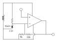
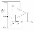
I have an inclinometer which is requires a +5v supply and earth, and it puts out a varying voltage of 2.2-2.8v centered at 2.5v.
Essentially, I would like to scale this output voltage to still be centered at 2.5 but go from 0-5v. The solution must use a +9v supply (pp3 battery). It must also be able to be built really small (approx 2"x2" max board size).
I am assuming it would be an op amp based circuit and whilst I have experience in practical electronics, this particular problem is really causing me some grief.
Any help would be so greatly appreciated.
Cheers
Grant
 

Thread Starter

bassgrant

Joined Nov 29, 2012
3
Nah not homework mate. I'm a 24 year old bass player /audioelectronics tech in need of assistance with an 'awesome' idea... :)
 

#12

Joined Nov 30, 2010
18,224
Is it enough to say, you need a rail to rail opamp, a 2.5 volt reference regulator, a 3k resistor and a 22k resistor? Set the 2.5 volt reference as the negative input of the opamp and use the 2 resistors to make the positive gain 1+ 22/3

This would be simpler if you can steal a 2.5 volt reference from the inclinometer.
 
Last edited:

crutschow

Joined Mar 14, 2008
38,503
If the OP wants the output to go from 0-5V for an input voltage of 2.2V to 2.8V, then you would want the reference voltage to be at the minimum output voltage of 2.2V, not 2.5V.
 

wayneh

Joined Sep 9, 2010
18,104
I have an inclinometer which is requires a +5v supply and earth...The solution must use a +9v supply (pp3 battery).
Just wondering how to reconcile those statements. A rail-to-rail op-amp was mentioned, I think, because you need output all the way to the upper rail if you want 5V out of an op-amp being supplied 5V. If it's running on 9V, you don't need to hit the upper rail.

So do you need everything powered off the battery, or is there 5V power already available for the inclinometer that you might also use for the op-amp circuit, or do they need to be completely isolated from each other?
 

ErnieM

Joined Apr 24, 2011
8,415
Sorry, I don't believe either circuit shown would work.

The span of the input is 2.8V-2.2V=0.6V to get an output range of 0 to 5V, so the gain is 5V/0/6V=8.333... You also need to subtract a constant of 2.2V from the input.

A conventional differential amplifier could do this:


Now to get this to work a 2.2V reference voltage is needed. If you don't have one handy...

Perhaps the 5V supply could serve as the reference, if it is stable for this application. To adjust the circuit for a different reference, I used a trick: I took the part of the circuit where the 2.2V ref comes in and viewed it as a Thevenin equivalent. Then I backed out to a voltage divider, 5V input, 2.2V output, and 600 ohm resistance. Solving for those parameters (not much algebra but a pain to type out) yields:


Resistor values are standard values for 1% leaded parts I found on Digi key.

Now it may be possible to adjust the 4 resistor version to eliminate one resistor, but that's more math then I'm in the mood to do right now. <grin>
 

Attachments

THE_RB

Joined Feb 11, 2008
5,438
maybe you could just do it in software?

0.6v range at the ADC input will be roughly 1024/5 *0.6 = 123 ADC counts for the full tilt of the sensor. Averaging a few samples with the system noise would give an ADC resolution of maybe 600 counts which is probably enough for the application?

All that is assuming you need the 0-5v for an ADC sensor input and not an analogue synth VCF/VCO etc.
 

#12

Joined Nov 30, 2010
18,224
This is the concept I tried to do in post #6, and I believe it will work.
I'm not even going to try to fix post #7.
I must have had a terrible case of brain farts that day!
 

Attachments

ErnieM

Joined Apr 24, 2011
8,415
Ah, now I see what you did. The "ground" symbol was confusing.

I would present that schematic as such:


I like it, it works on my paper.
 

Attachments

Top