 Facebook
 Google
 GitHub
 Linkedin
Hi
I'm trying to read the "lock" signal of the alarm. The one which locks the doors when pressing the lock button of the remote control of the car.
The car is 2008 Honda Civic.
I'm using arduino for the project, so I need to convert it to 5v.
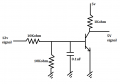
I built a circuit as in the picture attached.
First I tried reading the ACC of the car and it worked great. With Switch on , I got 0v in the output signal and with switch off, I got 5v in the output signal.
Then I tried to do the same with the "lock" signal.
I connected to the right wire. I measured about 12v fixed voltage from that wire. I assume that when locking the car, there's a pulse of 0v in that wire.
I couldn't measure it, but when connecting that wire to the car's ground I hear a relay closes and the doors indeed lock.
When I connected the input of my circuit to that wire, weird thing happened. The voltage on that wire, which was 12v fixed, became 6.4v fixed.
That was without touching anything. Just connecting.
So now I'm not sure what happened. So far I couldn't find the car's original wiring diagram of that circuit. Still looking for it.
I thought maybe someone here have experience with that matter and can give some advice.
I'm trying to read the "lock" signal of the alarm. The one which locks the doors when pressing the lock button of the remote control of the car.
The car is 2008 Honda Civic.
I'm using arduino for the project, so I need to convert it to 5v.
I built a circuit as in the picture attached.
First I tried reading the ACC of the car and it worked great. With Switch on , I got 0v in the output signal and with switch off, I got 5v in the output signal.
Then I tried to do the same with the "lock" signal.
I connected to the right wire. I measured about 12v fixed voltage from that wire. I assume that when locking the car, there's a pulse of 0v in that wire.
I couldn't measure it, but when connecting that wire to the car's ground I hear a relay closes and the doors indeed lock.
When I connected the input of my circuit to that wire, weird thing happened. The voltage on that wire, which was 12v fixed, became 6.4v fixed.
That was without touching anything. Just connecting.
So now I'm not sure what happened. So far I couldn't find the car's original wiring diagram of that circuit. Still looking for it.
I thought maybe someone here have experience with that matter and can give some advice.
Attachments
-
 19.2 KB Views: 17


