
Converting 0-2.5-5 voltage to 5-0-5 voltage

crutschow

Joined Mar 14, 2008
38,578
Is that essentially correct?
I think so.
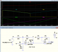
Below is the sim with added nodes plotted to help show its operation:
U1 is a gain-of-1 inverter with the output offset by +5V until its output reaches 0V, at which point the diode becomes reversed biased and the input directly drives U2, whose output is offset by -5V, with a non-inverting gain of 2.
1689007990616.png
 
Last edited:

BobTPH

Joined Jun 5, 2013
11,573
My circuit takes the original 0-5V signal and inverts it with the first opamp, giving a 5-0V signal. The two Schottky diodes take the max of those two signals with a loss of about 0.25V diode drop giving you the desired V shape from about 4.75V to 2.25V to 4.75V The second opamp offsets and scales this to get the desired 5 to 0 to 5. It is not a precision linear output due to the differing diode drop at different currents, but I think it is good enough for a joystick, which cannot do precise control anyway. The other posted circuits give more linear results.

I just had the idea for the max of two opposite direction ramps to get the V and wanted to see if it worked at all. When it worked better than expected, I posted it.
 

BobTPH

Joined Jun 5, 2013
11,573
Well, mine gets as close to 5V as the rail to rail opamp you use can.

As I said though, the other two are definitely more precise. I just wanted to try a novel approach.
 

crutschow

Joined Mar 14, 2008
38,578
I guess all of that over analyzing I did to understand the circuit just becomes academic to the more experienced designers.
Not at all.
Wanting to know exactly how a circuit works is something I do all the time, and these circuits were a little convoluted in their operation, so not particularly easy to understand.
I find simulating them and looking at the node voltages usually makes it much easier for me follow the circuit operation, which I did for sghioto's circuit.
 
Top





