Convert 12V/24V logic signal to 5V

Status
Not open for further replies.

Thread Starter

WylieZA

Joined Jan 16, 2018
8
I am trying to find a quick and simple way to convert a 12V/24V high or low signal to a 5V one.

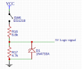
The input will be produced by a switch which will when closed will connect to Vcc which could be either 12V or 24V and I would like to convert this to 5V.

I have attached a rough schematic to show what I mean.

Some methods I have thought of:

Use the 12V/24V to switch a transistor, however the transistors I have looked at don't want to be switched by such a high voltage and they normally have around a 6V limit (Veb).

Another method could be to just point a linear voltage regulator on the signal such as a 7805 to convert the signal to 5V regardless of it's voltage. But I feel this may be bad design.

I would have simply used a resistor voltage divider but because I don't know if it is 12V or 24V this won't work.

I am a beginner and any helpful advice will be much appreciated.
Many thanks,
Justin
 

Attachments

LesJones

Joined Jan 8, 2017
4,174
You could use a potential divider with a 4.7 of 5.1 volt zener diode in parallel with the lower resistor. The values of resistors for the potential divider would depend on the logic family that you are using. You could use a transistor. The Vbe rating is for the reverse voltage across the junction. (For an NPN transitor how negative you can take the base with respect to the emitter. ) You will need a resistor to limit the base current and one to pull the base down to the negative rail. Using mechanical contacts you will also need to de bounce the signal unless you plan to do that in software.

Les.
 

smooth_jamie

Joined Jan 4, 2017
107
For logic level changing you can use optocouplers like the PC817. It is an LED and a phototransistor paired in an IC package. You put the 12V signal on the LED and gate a 24V source using the transistor on the opposite side. Make sure you limit the current to less than 50mA on the LED so it doesn't burn out.
 

Thread Starter

WylieZA

Joined Jan 16, 2018
8
You could use a potential divider with a 4.7 of 5.1 volt zener diode in parallel with the lower resistor. The values of resistors for the potential divider would depend on the logic family that you are using. You could use a transistor. The Vbe rating is for the reverse voltage across the junction. (For an NPN transitor how negative you can take the base with respect to the emitter. ) You will need a resistor to limit the base current and one to pull the base down to the negative rail. Using mechanical contacts you will also need to de bounce the signal unless you plan to do that in software.

Les.
Alright so let me confirm I understand.

NPN transistor method:

I can use the following circuit (see schematic) and the 2N3904 transistor will be happy if I apply a voltage of 24V to the base while the emitter is at zero volts. The only issue would be if I where to apply 6V or more to the emitter while the base is at zero volts. Is this correct?

Zener diode method:

Please see the schematic I drew for this, when I get 12V everything will be fine and the zener won't trigger. However when there is 24V I will get 9.8V on the zener which will trigger it, and although it won't drain all 9.8V surely a significant current will flow through the zener causing problems?

Many thanks,
Justin
 

Attachments

LesJones

Joined Jan 8, 2017
4,174
You are correct that if the emitter was at +6 volts when the bas was at zero then this could destroy the transistor. Also if you applied a negative voltage to the input of more than 6 volts it would destroy the transistor. Also you do not need such low value resistors for R13 and R14 30K woulf be OK. There is no problem with the current trough the zener diode. With 24 volts input the voltage across the 6K8 resistor will be 19 volts so the current through this resistor will be 19/6800 = about 2.8 mA As there is 5 volts across the 4k7 resistor there will be just over 1 mA flowing through it so the current trhough the zener will be about 1.8 mA. If the logic family is the old 74 series you would need to drop the 4k7 down to 470R (And the 6K8 to 680R) for it to be able to pull the input down low enough to be seen as alogic zero. The opto isolator is also a valid solution.

Les.
 

Thread Starter

WylieZA

Joined Jan 16, 2018
8
If the logic family is the old 74 series you would need to drop the 4k7 down to 470R (And the 6K8 to 680R) for it to be able to pull the input down low enough to be seen as alogic zero.
This is interesting, so how could I tell reading the data sheet what are the biggest value resistors I could use? Say if I where to want to use the SN74HC00N (http://www.ti.com/lit/ds/symlink/sn74hc00.pdf)

Also I don't quite understand why it is necessary because (although a small amount of current is required) I thought it worked off the voltage, so would it not be that the only different between using higher values resistors or lower value ones would be the time it takes for the chip to register a high or a low?

What would the / a new logic family series be?

Many thanks.
Justin
 

LesJones

Joined Jan 8, 2017
4,174
Any cmos logic family (Such as 4000 series or HC series) has a very high input resistance so even 1 megohm would work as a pull down or pull up resistor. Even though such high values would work using them would make it more susceptible to noise pick up. I would use about 10 K resistors.

Les.
 

mahdiar.m95

Joined Nov 22, 2018
1
For logic level changing you can use optocouplers like the PC817. It is an LED and a phototransistor paired in an IC package. You put the 12V signal on the LED and gate a 24V source using the transistor on the opposite side. Make sure you limit the current to less than 50mA on the LED so it doesn't burn out.

50mA limitation is very useful data. tanks a lot.
 

AlphaGeek

Joined Sep 6, 2020
5
I tend to run the average LED at about 25 mA, but I see these voltage dividers with low resistance, and always wonder why the values aren't higher. Yes, you have to have enough current to bias the BJT in this case, but I would build this with higher value resistors to reduce power consumption from waste heat generation - especially if I intended for it to run on battery power.
 

dl324

Joined Mar 30, 2015
16,845
Yeah, One of the was mine. Where did it go?
Apparently moderation deleted the two posts I referenced; making my post seem clueless...
Is it unacceptable to reply to old stuff? I was interested in discussing the way people design voltage dividers.
If you have something worthwhile to contribute it's okay. If not, it's frowned upon because people watching that thread (by contributing to it) will be summoned by a new post. That's why the text entry box has a warning about the post being old whenever you try to post to a thread that's considered old.

Most prefer to let old threads die. If you have a related question, you can start your own thread.
Not feeling very welcome.
Welcome to AAC!

There's a "Who are you?" thread in Off Topic for introductions. Just checked and it's pinned in that forum:
https://forum.allaboutcircuits.com/threads/who-are-you.78/page-95
 
Status
Not open for further replies.
Top