convert 0 to 5V square to square wave centered at 0V

Papabravo

Joined Feb 24, 2006
22,084
Hello,
I was trying to figure out equation for component selection for astable 555 mode given frequency and duty cycle but it seems it cannot be solved. Here is why.
The frequency is given by,
f = 1.44/((R1+2*R2)C) ---------->1
which gives, R1+2*R2=1.44/fC
The Duty Cycle is,
d = R1+R2/(R1+2*2R2) ------------->2
and using substitution R1+2*R2=1.44/fC solving for R1 gives,
R1= 1.44d/(fC) - R2 ----------->3

Using eqn3 given d,f,C and R2 does not give value R1 that is consistent with frequency and duty cycle from eqn1 and 2.

Meaning,for example, using eqn1 and eqn2 with R1=134kohm, R2=10kohm,C=1nF gives f=9.35KHz and d=93.51%.
while using eqn3 with d=50% i.e 0.5, f=5khz,C=1nF,R2=10kohm gives R1=134kohm. So using C=1nF,R2=10kohm gives R1=134kohm from here should give f=5khz and d=50% but is not,why?
You have 3 variables and only two independent equations. When this happens you can assign a convenient value to one of the components and compute the remaining values. Usually the capacitor is chosen because you have fewer options for obtaining a precise value. Resistors are more flexible in this regard. A careful perusal of the datasheet will contain "suggestions" for the selection of "reasonable resistor and capacitor values in the form of one or more graphs. In any case finding values that are "dead nuts" accurate is not likely to be possible.
 

Thread Starter

cktboy

Joined Apr 24, 2020
45
You have 3 variables and only two independent equations. When this happens you can assign a convenient value to one of the components and compute the remaining values. Usually the capacitor is chosen because you have fewer options for obtaining a precise value. Resistors are more flexible in this regard. A careful perusal of the datasheet will contain "suggestions" for the selection of "reasonable resistor and capacitor values in the form of one or more graphs. In any case finding values that are "dead nuts" accurate is not likely to be possible.
i did this, let me explain.
putting in some chosen component values in eqn(3) gives value of R1 but then if you independently put in same selected component values in eqn(1) and eqn(2) you get different frequency and duty cycle that you originally selected.
 

Papabravo

Joined Feb 24, 2006
22,084
i did this, let me explain.
putting in some chosen component values in eqn(3) gives value of R1 but then if you independently put in same selected component values in eqn(1) and eqn(2) you get different frequency and duty cycle that you originally selected.
Then you are going about it wrong. First things first. You have to determine how may "independent" equations you have. Then you have to determine how many independent quantities you have. In order for there to be a single unique solution the two numbers must be the same. If you have too many variables or too many equations, then you cannot find a unique and consistent solution.
 

AnalogKid

Joined Aug 1, 2013
12,187
I just noticed that we have two separate, but unrelated discussions going on in a single thread. How did this happen?
Don't know. Let's try something . . .

I have 0V to 5V square wave output from 555 timer. How to convert it with center at 0V, that is from -2.5V to 2.5V. I tried capacitor but I am getting -5V to 0V.
That does not make sense. Please post *your* schematic so we can see exactly what you have built.

ak
 

Thread Starter

cktboy

Joined Apr 24, 2020
45
Then you are going about it wrong. First things first. You have to determine how may "independent" equations you have. Then you have to determine how many independent quantities you have. In order for there to be a single unique solution the two numbers must be the same. If you have too many variables or too many equations, then you cannot find a unique and consistent solution.
there are 2 equations but the number of variables is 5 (f,C,R1,R2 and d), right? I had feeling about this relating number of variables and equation but just didn't go further into, but it looks this problem is about just that. back to high school.

i posted this question in separate thread but it got merged here by the moderator. anyway, still working on 555 timer, generating square wave of specified frequency centered at 0V.
 
Last edited:

crutschow

Joined Mar 14, 2008
38,593
To work from basics, you can calculate the time it takes for the capacitor to charge from 1/3 Vcc to 2/3 Vcc for the on-time, and the time it takes to discharge from 2/3Vcc to 1/3Vcc for the off-time.
The times are calculated using the RC exponential charge and discharge equations.
 

Thread Starter

cktboy

Joined Apr 24, 2020
45
I calculated the charging and discharging times and even build a calculator. I don't know the process of how to center the 0 to 5V square signal to center of 0V.
 

AnalogKid

Joined Aug 1, 2013
12,187
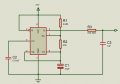
The schematic is below. I changed the frequency to 689KHz. How to center it at 0V from 0V-5V.
View attachment 268547
R3 and C3 are in the wrong places.

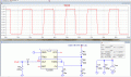
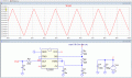
Swap R3 and C3. This makes C3 the output coupling capacitor, and R3 establishes an average value of 0 Vdc on the output side of C3. A 50/50 squarewave will be symmetrical about this value.

If you increase the value of R3 to something like 10K or 22K, the output will be more square. That is, it will have faster rise and fall times, and the flat parts of the waveform will have less droop.

If you had posted this image in post #1, you would have gotten the answer in post #2.

ak
 
Last edited:

Thread Starter

cktboy

Joined Apr 24, 2020
45
i posted the wrong schematic picture while doing some experimentation, yes the R3 and C3 are swapped in my other thread answers.
 
Top