You can use a small toy motor to drive a rotary switch every time you press the button.
No power is drawn when you release the button and it remembers the last position.
Actually it was a 74LS93 and a 1 of 8 decoder, but a CD4017B would be even simpler as mentioned by someone else here, because it has the decoder built in.
You need the transistors on the output of each decoder output though because the bulbs draw 1 amp.
You also need to have the device reset when it reaches a count of 6 if you only have 6 bulbs, using outputs '0' to '5' only, and '6' to reset to zero.
Last but not least, you cannot connect a switch directly to the CD4017B because it will cause erratic turn on of the bulbs which will appear to be uncontrolled. You have to debounce the switch. The easiest way is to use a momentary action pushbutton SPDT switch because that is much easier to debounce than a normally open SPST pushbutton switch. To debounce with an SPST switch you have to use a resistor and capacitor and it gets touchy on what values you choose, although if you do not need fast action that could work. Using an SPDT switch you can use a SET RESET latch to debounce the switch perfectly.
The switch has to be debounced because a regular switch will turn on and off many times when you press it before it comes to rest, and all of those on/off cycles cause the counter to increment by 1 count. With several on/off cycles the count could go from 1 to 5 in with just one push, or even 1 back to 1 with just one push, or even cycle around the count from 0 to 5 several times before it comes to rest on some random count like 4, even though the last count was at 5.
I think I covered everything mentioned in this thread by myself an others but to recap a little with due credits for the suggestions:
1. CD4017 or similar looks like a good choice (BobTHP).
2. MOSFET transistors to drive the bulbs (Eric).
3. Reset the CD4017 from the output '6' (Me).
4. Debounce the switch (Me).
5. Regular 9v battery is not a good idea (Cruts) as it is too weak to power a 1 amp bulb for very long, although maybe for a very short time only.
An old school approach: Use the CD4017 decade counter and a CD4081 Quad Dual input AND gate. One input goes to the 4017 clock and one goes to one of the two inputs of the and gate. The other input to the gate comes from the 4017 output. Since there are four chips in a package you'll need two of them to achieve six lights.
And I second the thought of ditching the incandescent lamps and go with LED. The battery has no chance of living for very long powering an incandescent lamp.
Here's a crude drawing of what I'm thinking: The large rectangle is the counter, the rounded gate is an AND gate and the tactile button is the - um - button. Each press of the tac will advance the output from one to the next. Each output will need its own gate with one input connected to the power rail and the other input connected to the output of the next sequential light to be lit up. This drawing lacks a WHOLE LOT of other parts. It's only meant to clarify what I'm thinking.
For six lights you'll need two chips (Quad Dual Input AND gate). You'll have 2 unused gates. Tie the extra inputs to ground OR to power. Don't leave them floating. They'll oscillate and destroy the chip.
Where is @sghioto when you need him? I am too lazy to draw up a schematic. The and gates will also work, as would a high side switch activated by the button. Does anyone know if the 4017 clocks on leading edge or trailing edge? It will make a difference in this circuit.
I think it depends on whether another lead is either grounded or powered. But that may apply to an up-down counter. From what I believe I recall it's a positive going edge. Don't shoot me if I'm wrong but that's where I'm putting money.
Where is @sghioto when you need him? I am too lazy to draw up a schematic. The and gates will also work, as would a high side switch activated by the button. Does anyone know if the 4017 clocks on leading edge or trailing edge? It will make a difference in this circuit.
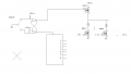
Here is a preliminary drawing.
The switch is a momentary pushbutton.
The IC is the now notorious CD4017B or similar.
MOSFETs are maybe 5 amp 20v devices with low RDS.
The output 6 connects to the reset pin on the IC.
The NAND gates are two within a CD4011B IC.
I’m trying to control 6 small light bulbs with one normally open push button switch. I want each bulb, but one at a time, to light for each press on the button, and to turn off when the button is released. I want this to happen in succession.
Not to be a picky snob but I believe the intent is to have the light on as long as the button is depressed. I also believe, and looks like you got it right Al, one light lights up at a time. This means - as forgive me - someone already said this - the 4017 has to be constantly powered otherwise it will reset to zero.
One last caveat, output zero should be not connected. This way starting off there are no lights illuminated. Speaking of illumination, I hope this has been enlightening.
WAIT A MINUTE AL - - - I just recognized the PMOS for temporary illumination. Oops. Looks good to me.
Actually it was a 74LS93 and a 1 of 8 decoder, but a CD4017B would be even simpler as mentioned by someone else here, because it has the decoder built in.
You need the transistors on the output of each decoder output though because the bulbs draw 1 amp.
You also need to have the device reset when it reaches a count of 6 if you only have 6 bulbs, using outputs '0' to '5' only, and '6' to reset to zero.
Last but not least, you cannot connect a switch directly to the CD4017B because it will cause erratic turn on of the bulbs which will appear to be uncontrolled. You have to debounce the switch. The easiest way is to use a momentary action pushbutton SPDT switch because that is much easier to debounce than a normally open SPST pushbutton switch. To debounce with an SPST switch you have to use a resistor and capacitor and it gets touchy on what values you choose, although if you do not need fast action that could work. Using an SPDT switch you can use a SET RESET latch to debounce the switch perfectly.
The switch has to be debounced because a regular switch will turn on and off many times when you press it before it comes to rest, and all of those on/off cycles cause the counter to increment by 1 count. With several on/off cycles the count could go from 1 to 5 in with just one push, or even 1 back to 1 with just one push, or even cycle around the count from 0 to 5 several times before it comes to rest on some random count like 4, even though the last count was at 5.
I think I covered everything mentioned in this thread by myself an others but to recap a little with due credits for the suggestions:
1. CD4017 or similar looks like a good choice (BobTHP).
2. MOSFET transistors to drive the bulbs (Eric).
3. Reset the CD4017 from the output '6' (Me).
4. Debounce the switch (Me).
5. Regular 9v battery is not a good idea (Cruts) as it is too weak to power a 1 amp bulb for very long, although maybe for a very short time only.
This thread went way over my head, but I’ll try to figure it out..
So I should use a SPDT switch instead of a SPST, however a SPDT switch will always keep one bulb glowing right? And if I want to be able to turn them off, so that no bulb is glowing, I could simply add a SPST switch to stop the electric flow without interfering with the CD4017? As long as it don’t stop the electric flow to the CD4017 (like pulling out the battery would) it won’t reset the CD4017 but let it remain state, is that correct?
And the reason why transistors is necessary, is because they amplify the electricity (AFTER leaving the CD4017) to the right current (in this case 1 amp), which is to high for CD4017B to handle, is that correct? And if so, what is used to lower the current BEFORE it reach CD4017?
1) Every push button that sequences through an operation needs to be debounced. Otherwise, the button will skip multiple states and will appear to be operating erratically. A SPST switch is the most common type of switch contact. This will give erratic operation.
Using a SPDT switch with additional circuitry gives reliable operation.
2) This has nothing to do with whether or not a lamp is lit under any condition. This is a separate design problem on its own.
3) Any logic gate cannot supply 1A to your lamps. You need additional circuitry such as transistors to drive your lamps. We are suggesting that you use LEDs instead of incandescent lamps. Whether or not you need additional transistors or ICs to drive the LEDs is another design issue.
Concept schematic. Two chips (not six), and one of them is nothing but transistor drivers.
As others have said, the CD4017 steps through a six-output sequence one output at a time. Q1 enables power to any lamp only when the switch is pressed.
R2-C2 debounce the signal into the Clock input. R2 also keeps the clock input held low when the button is not pressed.
For higher current lamps, replace U2 with 6 small power MOSFETs and six transient suppression diodes. Also, replace Q1 with a PNP power transistor.
At room temperature, the static current of the circuit when the button is not pressed is approx. 10 uA.
Note: 4017 chips from some manufacturers always power up in the 0 state (pin 3 low). However, this is not a defined characteristic of the part. If you want a guaranteed startup condition, a power-on-reset (POR) circuit can be added at pin 15.
The 4017 has a Clock input and a clock Enable input. When the enable input is low, the clock input advances the output on the positive-going edge. BTW, this is a Schmitt trigger input. AND, clearly documented but rarely discussed, when the Clock input is held high, the Enable input advances the output on the negative-going edge. Note that the enable input is not a Schmitt trigger.
This thread went way over my head, but I’ll try to figure it out..
So I should use a SPDT switch instead of a SPST, however a SPDT switch will always keep one bulb glowing right? And if I want to be able to turn them off, so that no bulb is glowing, I could simply add a SPST switch to stop the electric flow without interfering with the CD4017? As long as it don’t stop the electric flow to the CD4017 (like pulling out the battery would) it won’t reset the CD4017 but let it remain state, is that correct?
And the reason why transistors is necessary, is because they amplify the electricity (AFTER leaving the CD4017) to the right current (in this case 1 amp), which is to high for CD4017B to handle, is that correct? And if so, what is used to lower the current BEFORE it reach CD4017?
No problem people here will help you through it all the way.
Yes, a momentary pushbutton SPDT is better to use than a SPST pushbutton because it is more reliable and nearly fool proof for obtaining just one clock pulse per push.
They will all be off until you push a button, but you should keep the CD4017B energized until you are done using the circuit, then you can shut that off too.
Yes, keep the CD4017B powered up.
Yes, transistors allow the proper current to get to the bulb when you push a button.
You do not need anything to lower any current to the CD4017B nothing provides a high current to that device.
I should note that the microcontroller solution, number 2 in @MrChips post #2, has not been explored further. It would result in simpler hardware and the behavior could be changed if necessary just by reprogramming.
So, to @NoKnowledge, are you familiar at all with microcontrollers and programming?
 Facebook
 Google
 GitHub
 Linkedin