controller implementation with op amps

Thread Starter

george12

Joined Mar 14, 2015
3
Hello to everybody. I have to do a project in automatic control and I've stuck a little.The situation is this:
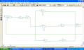
We have a transfer function G(s)=3750/((s+10)*(s+30)*(s+100)) and we must design a controller so that the output of the closed loop system follows the input as faster as possible. Then we need to implement the closed loop system with operation amplifiers with Vcc=12V.We have decided that the controller is 8.66*(s+10)*(s+30)/(s*(s+40)) . The problem is that the exercise also requires that with a small change in the controller if the input is a step function from 0 to 5 volts the output to go to 5 volts not as fast as possible this time (of course we want none stage to fall to saturation). We thought that we can change the gain of the controller with a variable resistor and make it smaller but the simulation with pspice gives an output of 1.6 volts but we want 5. What do we need to change?
Please answer as soon as possible
 

Papabravo

Joined Feb 24, 2006
21,225
I would suggest a root locus plot. Then you can plainly see how the roots need to be relocated to achieve your objective(s).
 

t_n_k

Joined Mar 6, 2009
5,455
This is presumably a school project. It should go to the homework forum.
You need to clarify a couple of matters and show a control loop diagram so that we can verify your statements thus far.
How did you arrive at 1.6V & where is that value observed?
 

Thread Starter

george12

Joined Mar 14, 2015
3
here is the pspice file in two pieces:

upload_2015-3-15_11-38-35.png
upload_2015-3-15_11-4-19.png

and here is the block diagram of the closed loop system:
cls.jpg
here is the pspice file Schematic2.sch
comments: the first op amp exist to subtract the feedback from the output
then the other six op amps in the first image implement the controller 8.66*(s+10)*(s+30)/(s*(s+40)) with simple fraction decomposition. Then in the second image the first op amp multiplies the negative previous sum of the partial fractions with -1 so that we have the right result and then the 4 last op amps are for G(s)=3750/((s+10)*(s+30)*(s+100)) and we implement G(s) in 3 stages 5/(s+10),15/(s+30),50/(s+100) and the last op amp exists to invert the result.
The exercise wants :
1) for input step function from zero to one to have a response that goes to 1 the faster you can
2)with a small change (probably) to the controller for input a step function with whatever range between -5 and 5 the output to follow the input and none of the stages must fall into saturation.

Tell me can these be achieved with a little change for example by reducing the gain of the controller with a variable resistor that will be added before the controller-we tried that in pspice but the output follows the input only until 2.2 volts it can't go higher and apart from that if we reduce the gain of the controller we don't fall into saturation but the output doesn't follow the input or do we need to change controller (the question 1) works but 2) doesn't in our circuit)
 

Attachments

t_n_k

Joined Mar 6, 2009
5,455
It's fairly obvious you won't satisfy the saturation caveat with the design as you present it.
With a +5V step input the loop error (summing junction output) at t=0 sec would also be +5V. The proportional branch of the controller will produce a controller output (without any dynamic limits) of 8.66x5 Volts or 43.3V at t=0 sec, which is clearly greater than the highest achievable op-amp output with Vcc=+12V supply to the op-amps. You also haven't indicated whether the op-amp supply is bipolar +/- 12V.
Again, you haven't indicated the overall design constraints for the final closed loop system - you simply state that the output must reach the input demand value in the shortest time. Normally one might anticipate other design constraints for consideration such as allowable overshoot, steady state error and settling time.
 
Last edited:

Thread Starter

george12

Joined Mar 14, 2015
3
for the supplies: we have op amps 741 with a supply 12V and an other -12V and there are two only constraints: 1) steady state error zero for a step function with whatever range between -5V and 5V (for example from -5 to -2) and 2) for an input step function from 0 to 1 this time the steady state error to be 0 and the response to be the fastest.That's all the constraints.
If you find a better controller that will satisfy the above let us know. Thank you for your help and if there is something I don't explain well enough write me
 

Papabravo

Joined Feb 24, 2006
21,225
I don't think you understand the fundamental problem. When you run into a scaling problem that causes the response to be outside the realizable range of voltages and currents you need to do something. One approach is to scale the original problem by a factor of 10 for example. Now you have a realizable solution which can be re-scaled if necessary. You don't suppose the guys doing flight controls just give up when the equipment is not up to the task do you? Nah, they just build better equipment.
 

t_n_k

Joined Mar 6, 2009
5,455
@george12
Perhaps English is not your native language and something has been lost in translation.
Unfortunately your specification is confusing.
Why would the dynamic behavior change simply because the step input range is different? Granted, the various voltage amplitudes will differ but their general form (rise time, % overshoot, settling time) would be consistent whether the step input was from 0V to 1V or from -5V to +2V - provided there were no saturation (dynamic limit) problems.
Unless you can clarify the specification it's going to be hard to offer assistance.
I'll repeat my earlier point about this looking very much like class work or homework. If so, you need to acknowledge this and have the thread moved to the homework forum.
Otherwise you might find forum members (including me) even less responsive to your questions.
 
Last edited:
Top