Controlled Current Source

Thread Starter

AetherNZ

Joined Mar 23, 2008
21
I am trying to design a triangle wave generator for a university project.

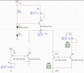
I am using the attached circuit to generator the wave and a similar setup to above for each current source. Currently by varying R2 of both current sources at the same time the frequency is changed.

The specs state that the generator must have 20-80% duty cycle control. Which would work for the original design if you vary R2 in different proportions but this isnt very elegant.

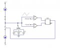
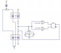
So I was thinking of the other attached design as a solution. The main current source would be varied the same way as before. Then the current could be proportionally split and the other two current sources would mirror each side. This way the frequency would same the same but the duty cycle would change with only 2 knobs.

Would this work? How could I implement the current-controlled current-sources?

Is there a more elegant way of accomplishing the task?

Thanks :cool:

Note: I accidentally didn't hook up /Q to the switch but you get the idea.
 

Attachments

John Luciani

Joined Apr 3, 2007
475
Your schematic is a current-sink not a current-source. A better way to do this would
be to use an op-amp. With a control voltage you could vary the current.
There is a schematic of a current sink (a.k.a load cell) at
http://www.luciani.org/geda/util/matrix/index.html

Just scroll down the page and look for the load-cell.

If you want a fixed current I would use a TL431. The TL431 current-sink schematic
looks similar to your schematic.

(* jcl *)
 

Thread Starter

AetherNZ

Joined Mar 23, 2008
21
Thanks for your reply John.

I forgot to mention that idea behind the project is to get back to fundamentals so the less ICs the better.

Ah I always get the current sources and sinks mixed up haha.

I looked into using an integrator but a lot of the manufacturers seem to use the current-source/sink method.
 

hgmjr

Joined Jan 28, 2005
9,027
Thanks for your reply John.

I forgot to mention that idea behind the project is to get back to fundamentals so the less ICs the better.

Ah I always get the current sources and sinks mixed up haha.

I looked into using an integrator but a lot of the manufacturers seem to use the current-source/sink method.
Are you saying that you are required to use discrete components only or can you use ICs?

hgmjr
 

Thread Starter

AetherNZ

Joined Mar 23, 2008
21
ICs are allowed but discrete transistor-type circuits preferred.

Eg where I have used comparators in the conceptual design I would actually just use a transistor differential amp in the detailed design.

Thanks
 

hgmjr

Joined Jan 28, 2005
9,027
You may want to look into current-mirror circuits. You can construct them from dual matched transistors that can be found in a single package.

You could use one current mirror composed of dual NPN transistors in the same packake as a current sink and one current mirror composed of dual PNP transistors in the same package as a current source. I stress matched transistors because this is the best way to insure that the transistors track each other over temperature.

hgmjr
 

Thread Starter

AetherNZ

Joined Mar 23, 2008
21
Thanks for the reply. Yea I have been looking into current mirrors and have taken your advice and built the current-sink mirror using the NPNs which is working.

Im not sure how to wire the current source mirror since the control side of the mirror will be sinking and the driving side will be sourcing so their bases can't simply be connected(the top current-controlled source in theory diagram)??
 

Thread Starter

AetherNZ

Joined Mar 23, 2008
21
This is what I have got so far.

R2 & R3 are just variable test loads.

R4 sets total current.
R1 splits current in each branch.

Am I on the right track? Dont know how to do the other half??
 

Attachments

Last edited:

SgtWookie

Joined Jul 17, 2007
22,230
Love the drawing Hgmjr...

A straight op amp integrator is a constant current source to the cap.

Bill,
Have you actually built that circuit?

I'm trying to simulate it, and without swapping the inverting and noninverting inputs to the opamp, it won't oscillate. With the opamp at unity gain, the triangle wave it puts out really looks dismally bad - more like a sine wave with a lopped-off negative peak.

Originally, I supplied the 555 timer with 10v, and the op amp with +/-10v, but both peaks were truncated.
In order to prevent truncation of the positive peak, I reduced Vcc to the 555 to 5v. It's still truncating the negative peak.
 

Thread Starter

AetherNZ

Joined Mar 23, 2008
21
This is along the lines of what I was thinking about.

You will need to tweak it a bit.

hgmjr

That's the same circuit I came up with but I couldnt think of a way to scale both of the current mirrors so that you could adjust the frequency.
 
Top