 Facebook
 Google
 GitHub
 Linkedin
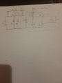
Attached is a a boost converter and inverter cascade. I have modelled and simulated the 2 level interleaved boost converter successfully. However, I'm experiencing problems with the small signal analysis of the h bridge inverter (spwm 400v dc - 230v ac switching at 50KHz for max load of 700W). I would like to employ dual loop control with the inner loop being the current control loop. Kindly assist with the small signal modelling of the inverter.
Attachments
-
 58.1 KB Views: 3


