Facebook
 Google
 GitHub
 Linkedin
Hi everybody,
in my current project, I want to apply a voltage to a capacitor (top electrode on a thin film heterostructure) very rapidly. Since capacitors have their own charging rate (τ = R ⋅ t = R ⋅ ε_r ⋅ ε_0 ⋅ A/d) and the only variable I can access is A, I need to keep the area as small as possible. In my case, I have 50 Ohm impedance, ε_r ≈ 200 and the distance d between the electrodes is 100 nm. To achieve a reasonable time constant τ, the area of my nearly spherical electrode should be less than 30 μm^2.
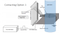
In my special case, I want to probe the area of the electrode with a laser shortly after the application of the voltage pulse. Thus, I cannot contact the electrode in the middle or with a thick wire. In my current plan, I design the shape of the electrode such that it is circular with a tail of 2x2 μm and I contact only the tail. However, I cannot think of a way to contact this small area without violating the impedance match or increasing the total area of the electrode.
Is there anybody with experience in this who can help me? Since I am not an electrical engineer, I would be very grateful, if the answers are as detailed as possible.
Thanks in advance,
cheers,
Marvin
in my current project, I want to apply a voltage to a capacitor (top electrode on a thin film heterostructure) very rapidly. Since capacitors have their own charging rate (τ = R ⋅ t = R ⋅ ε_r ⋅ ε_0 ⋅ A/d) and the only variable I can access is A, I need to keep the area as small as possible. In my case, I have 50 Ohm impedance, ε_r ≈ 200 and the distance d between the electrodes is 100 nm. To achieve a reasonable time constant τ, the area of my nearly spherical electrode should be less than 30 μm^2.
In my special case, I want to probe the area of the electrode with a laser shortly after the application of the voltage pulse. Thus, I cannot contact the electrode in the middle or with a thick wire. In my current plan, I design the shape of the electrode such that it is circular with a tail of 2x2 μm and I contact only the tail. However, I cannot think of a way to contact this small area without violating the impedance match or increasing the total area of the electrode.
Is there anybody with experience in this who can help me? Since I am not an electrical engineer, I would be very grateful, if the answers are as detailed as possible.
Thanks in advance,
cheers,
Marvin