Facebook
 Google
 GitHub
 Linkedin
Hello,
I extracted this fragment from the textbook Switching Power Supply Design, Abraham I. Pressman:
With MOSFETs, turnoff switching losses are considerably less than those with bipolar transistors. Current fall time with a MOSFET is so rapid that current in it will have fallen almost to zero by the time the voltage across it has risen significantly. Thus, although turnoff snubbers are used with MOSFETs, their prime function is not to reduce overlap dissipation, which is already low. Rather, the function of the MOSFET turnoff snubber is to reduce the amplitude of the leakage inductance voltage spike. Since leakage inductance voltage spikes are proportional to dI/dt in the transistor, a MOSFET with much faster current turnoff time than a bipolar will have a larger voltage leakage spike.
I would like to add that some new MOSFETs claim to have improvements on their dv/dt and di/dt capability.
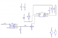
As stated in one of my previous posts, I'm going to use this one: IRF250P224.for a PMDC Brushed motor control application.
Do you think that a snubber is strictly necessary in my application? I know that it could bring somo improvements somehow, maybe not noticeable. It will of course reduce overall efficiency in the MOSFET.
I extracted this fragment from the textbook Switching Power Supply Design, Abraham I. Pressman:
With MOSFETs, turnoff switching losses are considerably less than those with bipolar transistors. Current fall time with a MOSFET is so rapid that current in it will have fallen almost to zero by the time the voltage across it has risen significantly. Thus, although turnoff snubbers are used with MOSFETs, their prime function is not to reduce overlap dissipation, which is already low. Rather, the function of the MOSFET turnoff snubber is to reduce the amplitude of the leakage inductance voltage spike. Since leakage inductance voltage spikes are proportional to dI/dt in the transistor, a MOSFET with much faster current turnoff time than a bipolar will have a larger voltage leakage spike.
I would like to add that some new MOSFETs claim to have improvements on their dv/dt and di/dt capability.
As stated in one of my previous posts, I'm going to use this one: IRF250P224.for a PMDC Brushed motor control application.
Do you think that a snubber is strictly necessary in my application? I know that it could bring somo improvements somehow, maybe not noticeable. It will of course reduce overall efficiency in the MOSFET.