Connection in parallel(noob question)

Thread Starter

blackout84

Joined May 4, 2013
2
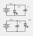
Are those two ways of connecting components in parallel are equivalent?
and if they are equivalent, are they equivalent for all types of load(for example a motor driver instead of the led)?

Thanks.
 

Attachments

MMH

Joined Feb 8, 2013
143
The difference is that electricity will first reach the LED a few microseconds before it reaches the capacitor in VCC1. Whereas, electricity will first reach the capacitor a few microseconds before it reaches the LED in VCC2. Usually, the cap is drawn first(VCC2). However, in real life, both of them will give the SAME results.:):)

Sorry for blabbering so much.:p:p
 

MrChips

Joined Oct 2, 2009
35,180
The difference is that electricity will first reach the LED a few microseconds before it reaches the capacitor in VCC1. Whereas, electricity will first reach the capacitor a few microseconds before it reaches the LED in VCC2. Usually, the cap is drawn first(VCC2). However, in real life, both of them will give the SAME results.:):)

Sorry for blabbering so much.:p:p
Sorry, that answer is completely incorrect.
The propagation delay in a piece of wire is about 3ns per metre.
 

tubeguy

Joined Nov 3, 2012
1,157
Welcome blackout84,

One more tip.

You have drawn an LED, pointed correctly, but without any current limiting device. An LED usually needs a current limiting device in series with it, such as a resistor, or a constant current source.
 

MrChips

Joined Oct 2, 2009
35,180
If you draw the circuit in the following manner maybe you will understand that it does not matter where you place the parallel elements.


An understanding of basic electricity, electronics and circuit layout will allow you to answer the question.
 

WBahn

Joined Mar 31, 2012
33,196
As tubeguy noted, the actual circuit would almost certainly not work well because of the lack of a current limiting resistor in series with the LED. But that is a side issue relative to the question you are asking. Just be aware that by ignoring it in our answers we are not implying that you can ignore it in your circuits.

For virtually anything you will ever be involved in the two are indistinguishable in any practical way. The only real difference is that the wires between the two at the top and bottom are carrying different currents in the two cases. In very rare and unusual situations this may have relevance in terms of noise or other subtle things. But these are issues that a schematic, by itself, does not address since someone constructing the circuit based on the schematic has complete freedom to hook it up any way they want as long as it agrees with the schematic functionally. So, when subtle issues like signal routing matter, much more care must be taken to represent those issues and their solutions in the schematic.
 

MrChips

Joined Oct 2, 2009
35,180
To follow up on what WBahn has said, it is customary in good circuit construction to include two capacitors in parallel across the power supply lines, a 0.1μF and a 10μF capacitor.

In the schematic drawing you can place them in any order.

The actual placement on the circuit board can make a huge difference in the performance of the circuit.
 

WBahn

Joined Mar 31, 2012
33,196
That's a really good example. The very reason that two capacitors (and in sensitive circuits maybe three or four "decade-tiered" bypass caps) are needed is tightly coupled to this very issue.
 

MMH

Joined Feb 8, 2013
143
Sorry, that answer is completely incorrect.
The propagation delay in a piece of wire is about 3ns per metre.
It is not COMPLETELY incorrect. For instance, what if the wire is 1km long-then it will be 3ns x 1000=3micro sec. Am I right?? I know it is close to impossible:p:p
 

Thread Starter

blackout84

Joined May 4, 2013
2
I was hoping for this answer - saved me allot of resoldering :)
I'm fully aware of the need of caps and a current limiting device for a real world applications.
Thanks you guys for the detailed answer
 
Top