configuration of a NPN amplifier transistor...

configuration of a NPN amplifier transistor?

  • common emitter

    Votes: 2 100.0%
  • common collector

    Votes: 0 0.0%

  • Total voters
    2

Thread Starter

alaa7assan

Joined Sep 16, 2017
4
hey guys..
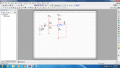
I need help in understanding this circuit what is its amplifier configuration?
i have attached an image of the circuit it seems to be a common emitter as the input is on the base and the output is on the collector but when i ran the stimulation and connected my oscilloscope, i found out that the gain is less than 1 which is a characteristic of a common collector...


upload_2017-11-25_12-18-38.png
please take a look at the waveforms produced upload_2017-11-25_12-18-18.png
 

Attachments

crutschow

Joined Mar 14, 2008
34,285
Your post is such a low resolution that I can't read the part values, but it looks like you have an emitter resistor equal to the collector resistor.

Yes, it's a common emitter circuit but the gain of that circuit is approximately the collector resistor divided by the emitter resistor, so if they are equal, the gain will indeed be close to one (actually equal to the common-collector gain).
 

UnnamedUser159

Joined May 3, 2016
501
if i have understood right my teachers there is some trick about that. You have to watch the pin that goes to ground.
If course i am not sure 100% of this.

Of course about the types of bipollar transistors configuration you can search WwW, for example wikipedia
 

DickCappels

Joined Aug 21, 2008
10,152
This one is simple -the signal goes into the base and comes out of the collector, and the emitter is the common connection.

In a common collector configuration the collector is not connected to the input or output.

You can guess what we can say about the common base configuration.
 

AlbertHall

Joined Jun 4, 2014
12,345
The pin connected to ground is not a reliable indicator. The circuit below is grounded emitter but it is also common collector and has the characteristics you would expect from common collector.

In a common collector configuration the collector is not connected to the input or output.
Again this isn't true for the circuit below.
upload_2017-11-25_10-44-2.png
 
Top