computer controlled rgb leds

Thread Starter

slisgrinder

Joined Dec 7, 2008
45
yup that looks great. now onto the driver circuit...since i already ordered the mosfets (IRF540), what is a driver circuit anyway...

since the arduino supplies 5V at 40mA max to the gate, do i really need a driver circuit?
 

SgtWookie

Joined Jul 17, 2007
22,230
yup that looks great. now onto the driver circuit...since i already ordered the mosfets (IRF540), what is a driver circuit anyway...

since the arduino supplies 5V at 40mA max to the gate, do i really need a driver circuit?
IRF540 MOSFETs are standard N-channel MOSFETs. They will not work properly unless Vgs reaches 10v. This is why I specified logic level MOSFETs.

Now, IRL530's, IRL640's are also logic-level MOSFETs. Notice the "L" instead of the "F". That one letter makes a big difference.

Ordering the wrong MOSFETs will cause the circuit to be unnecessarily complicated.

Why don't you order some IRL530 or IRL540 MOSFETs from Digikey? They will ship them quickly, and this will keep your project much more simple.
 

SgtWookie

Joined Jul 17, 2007
22,230
what about an irl510?
That might work, but it has a much higher Rds(on) than the 530's and 540's. This means more power loss in the MOSFET, which means greater power dissipation. If you want the MOSFETs to run cool (which you do!) then use MOSFETs with a low Rds(on).

The IRLZ24 and IRLZ34 are less expensive than the IRL530/IRL540. But for some unknown reason, you seem to like to choose other parts than what are recommended.
 

Thread Starter

slisgrinder

Joined Dec 7, 2008
45
well, the irf540 are on their way...i guess i will have to use those...the supplier (lee electronics, the closest to where i live (calgary)) only has irl510 but not in stock so i guess i will have to use a driver circuit and stick with the irf540...
 

Thread Starter

slisgrinder

Joined Dec 7, 2008
45
how do you accomplish this? by having a transistor, and since this is a pwm signal, a transistor wouldnt work so...what am i suppose to do...i thought the gate-source voltage was +-20V?
 

SgtWookie

Joined Jul 17, 2007
22,230
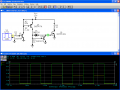
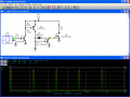
See the attached schematic.

V1 is just a signal generator, but it represents the 0v-5v output of your Arduino uC.

The rest is to handle the charging/discharging of the MOSFET's gate.

The 1N4148 really should be a 1N4150. A 1N4148 won't handle enough current.

R5 represents the load.
 

Attachments

SgtWookie

Joined Jul 17, 2007
22,230
so this schematic you just made it for the irf540? wow, thats cool...
No, it's a schematic I'd made up a year or so ago. It originally had an IRF730 MOSFET, I just changed that to an IRFI540G (basically the same as an IRF540, except it has an insulated heat sink tab) and re-ran the simulation.

Changes I've made in a newer simulation:
R1 = 1k
R2 = 2.2k
R3 = 10k
D1 => 1N4150
Q3 => 2N2907A
Q4 => 2N2907A

It works better that way.
 
Last edited:

Thread Starter

slisgrinder

Joined Dec 7, 2008
45
so since the gate to source voltage is +/- 20V on the IRF540, i would have to bump up the voltage from the signal from the arduino, but then what does the gate threshold voltage mean, on the spec sheet it says 2.0V to 4.0V?
 

SgtWookie

Joined Jul 17, 2007
22,230
Here, read this MOSFET Application Note:
http://www.national.com/an/AN/AN-558.pdf

Don't worry if you don't understand everything. But it will help you to get a better "handle" on how MOSFETs work.

Logic-level MOSFETS came about after that application note was written.

You could also use IRLU7807Z MOSFETs. Digikey has lots of them in stock:
http://www.digikey.com/scripts/DkSearch/dksus.dll?PName?Name=IRLU7807ZPBF-ND
Even cheaper than my prior recommendations, and you wouldn't need the driver circuit.
If you bought 10, you'd pay $0.72/ea. No heatsinks needed, either.
 

SgtWookie

Joined Jul 17, 2007
22,230
so since the gate to source voltage is +/- 20V on the IRF540, i would have to bump up the voltage from the signal from the arduino, but then what does the gate threshold voltage mean, on the spec sheet it says 2.0V to 4.0V?
The Vgs of +/- 20v you're seeing is the absolute maximum rating, or "Don't exceed this voltage unless you like to break things." :eek:

The threshold voltage varies considerably from MOSFET to MOSFET. You want to stay well above or below the threshold voltage when you are using a MOSFET as a voltage-controlled switch. For an enhanced MOSFET (typical nowadays) when Vgs=0, it is completely off.

Power MOSFETs can be used in the linear region, however they will dissipate a lot of heat. Unless you have them attached to a rather large heat sink, they will burn up. If you try to use your IRF540 MOSFETS with a Vgs of 5v and no heat sink in your application, you will burn them up.
 

Thread Starter

slisgrinder

Joined Dec 7, 2008
45
ok, so how does the driver circuit increase the voltage of the arduino pwm signal with the schematic you gave me when only +12V is being supplied?
 

Thread Starter

slisgrinder

Joined Dec 7, 2008
45
so if its going to burn up, then y do i need to use a driver circuit between the arduino and the mosfet...unless i have things seriously wrong...is the 5 v to the gate too much?


for the schematic of the driver circuit, is it ok to replace the diode with a 1n4001?
 

SgtWookie

Joined Jul 17, 2007
22,230
ok, so how does the driver circuit increase the voltage of the arduino pwm signal with the schematic you gave me when only +12V is being supplied?
Follow along in the attached schematic.

V1 is the simulated 0v/5v Arduino output. It's voltage is represented by the yellow (A) trace in the simulation below.

R1 limits the base current of Q2 to around 4.3mA, which is enough to saturate the transistor and safely limit the Arduino's output current.

R3 keeps the base of Q3 pulled high when Q2 is not conducting.

R2 limits the base current of Q3 when Q2 is conducting.

D1 provides a charge path to the gate of Q1 when Q3 is conducting.

R4 causes Q4 to turn ON (thus draining the gate charge of Q1) when Q3 is not conducting.

If you don't understand this, you should download a SPICE simulator and play with it. LTSpice is a very good (and free) SPICE simulator.
Download it here:
http://www.linear.com/designtools/software/ltspice.jsp

You can add devices to it if you need to. I'm sure Ron_H will be happy to guide you in that regards.
 

Attachments

SgtWookie

Joined Jul 17, 2007
22,230
so if its going to burn up, then y do i need to use a driver circuit between the arduino and the mosfet...
If you do not use a proper driver circuit between the Arduino and the MOSFET, it will burn up.

unless i have things seriously wrong...is the 5 v to the gate too much?
No, it is not enough. That is the purpose of the driver circuit.

for the schematic of the driver circuit, is it ok to replace the diode with a 1n4001?
A 1N4001 likely won't be fast enough. That is a power rectifier, not a switching diode.
A BAT54 would be a better choice, as it's a Schottky diode - but it would be hard for a hobbyist to deal with.
You might find 1N5817 Schottky diodes on the surplus market, which would also work a treat.

It sure would be easier if you would just order the right MOSFETs. :rolleyes:
 
Last edited:
Top