computer controlled rgb leds

Thread Starter

slisgrinder

Joined Dec 7, 2008
45
thankx for all the help,


i just ordered an arduino "2009" (can't wait to plug it in!!!), 1 ohm resistors, 16 1 watt Green LEDs, 16 1 watt Blue LEDs, 16 1 watt Red LEDs, and 100 ft of 22 guage wire...


now when i start wiring, i should connect the:
1) arduino pin to the gate of the mosfet with a 200 ohm resistor in between
2) connect the 12V source to the collector of the mosfet as well as the led chain's + line
3) connect the emmiter of the mosfet to the common ground as well as the "-" of the led chains

are my above steps correct?

and finally i am still lost as to how i am supposed to calculate the current limiting resistor value???
 
Last edited:

SgtWookie

Joined Jul 17, 2007
22,230
i just ordered an arduino "2009" (can't wait to plug it in!!!), 1 ohm resistors, 16 1 watt Green LEDs, 16 1 watt Blue LEDs, 16 1 watt Red LEDs, and 100 ft of 22 guage wire...
What are you planning on doing with the 1 Ohm resistors? I don't see where they'll be useful for much of anything.
now here is the "planned" schematic:

is the schematic correct?
You didn't upload the schematic; you tried to link to a file on your computer's desktop.

As a result, you are the only person who can see it.
 

leftyretro

Joined Nov 25, 2008
395
wow even i can't see the schematic...
i should be able to upload it to somewhere...
there this should hopefully work...


http://www.flickr.com/photos/94509166@N00/3116811907/


i know somewhere in my guts that the schematic is wrong...
By all means don't build your circuit to that drawing. Micro turns on gate, FET shorts out power supply and burns up. Were you wishing for the micro to be able to turn on and off the LED's? If so that won't work. ;)

Lefty
 

Thread Starter

slisgrinder

Joined Dec 7, 2008
45
"Were you wishing for the micro to be able to turn on and off the LED's? If so that won't work. ;)"

no i am trying to pwm them using the arduino...
 

leftyretro

Joined Nov 25, 2008
395
what about these schematics:

http://www.flickr.com/photos/94509166@N00/3117669998/
http://www.flickr.com/photos/94509166@N00/3116843009/

which one is right if none, how a i supposed to correctly wire them?
No, none of those will work as drawn.

"how a i supposed to correctly wire them"

By studing and learning from other drawings. Below is a drawing from the Arduino playground site. There is tons of information on the Arduino site if you will take the time to search and read, that is how real knowlege is gained.

This circuit comes close to what you want to do. It's using a NPN transistor but a MOSFET can be used in place of it. Look at the current paths and pay attention to polarities and direction of diode arrows, etc.

http://www.arduino.cc/playground/uploads/Learning/multiple_leds2.jpg


Good luck

Lefty
 

SgtWookie

Joined Jul 17, 2007
22,230
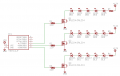
Well, you want it more like the attached schematic.

The controller I used in the schematic is an Atmel Tiny 11 just as an example. I have no idea about Arduinos, so you'll need to ask someone else about that.

The LED current limiting resistors have no resistance values, because I do not know what you will need.

Note that the red, green, and blue LEDs are controlled by different logic-level N-channel MOSFETs.

Just to help you keep them straight as a rough comparison:
Rich (BB code):
MOSFET   Transistor
Drain  = Collector
Gate   = Base
Source = Emitter
But that's just an extremely rough comparison.
MOSFETs control the current from the source to the drain by the voltage on the gate. In a steady state, there is virtually no gate current.
Transistors control the collector current by the current flowing in the base.
 

Attachments

Last edited:

Thread Starter

slisgrinder

Joined Dec 7, 2008
45
wait how come the cathodes of the leds are connected to the drain? isn't it supposed to be the anodes to the drain and cathodes to the power source?

also the pins on the arduino is the same as what you have in the schematic just a different number...

also what do you mean by a steady state? constantly on?
 

Audioguru

Joined Dec 20, 2007
11,248
The blue LEDs are 3.4V to 3.6V. Four 3.6V LEDs in series need a supply of 14.4V plus a couple of volts for the current-limiting resistor. But the supply is only 12.0V so use only two or three blue LEDs in series and in series with a current-limiting resistor.
 

SgtWookie

Joined Jul 17, 2007
22,230
The blue LEDs are 3.4V to 3.6V. Four 3.6V LEDs in series need a supply of 14.4V plus a couple of volts for the current-limiting resistor. But the supply is only 12.0V so use only two or three blue LEDs in series and in series with a current-limiting resistor.
That's a problem, because our OP changed everything in mid-thread.

He's now using 350mA LEDs, and hasn't posted the datasheets for them.

The schematic I posted is just a rough conceptual schematic. The actual layout is going to depend upon the typical Vf @ current rating for the various colors.

As you've implied, he'll probably have to split up the blue LEDs into two or more parallel strings, each with their own resistors.
 

SgtWookie

Joined Jul 17, 2007
22,230
wait how come the cathodes of the leds are connected to the drain? isn't it supposed to be the anodes to the drain and cathodes to the power source?
In the project you were looking at before, the author was using RGB LEDs that had a common cathode. Because they had common cathodes, he had to use P-channel MOSFETs and drivers for their gates.

However, you are using individual red, green, and blue LEDs, instead of all three colors in one LED - unless you have mis-informed us. Are they individual LEDs, or are they RGB LEDs?

With individual LEDs, you can use logic level N-ch MOSFETS, which simplifies your circuit a good deal. You can also use N-ch MOSFETS with RGB LEDs, if they are common anode. The circuit layout would be quite different though; each color on each LED would need it's own resistor.

also the pins on the arduino is the same as what you have in the schematic just a different number...
That's just random chance :)

also what do you mean by a steady state? constantly on?
Constantly on or constantly off.

The gate of a MOSFET acts electrically like a capacitor (not exactly, but close). You charge it to some voltage to turn it on, and discharge it (until Vgs=0) to turn it off. At high frequencies, it can take a good bit of current flow to charge/discharge the gate.

Typical MOSFETs require Vgs=0 to be fully turned off, and Vgs=10 (-10 for P-ch) to be turned fully on. Logic-level MOSFETs only need Vgs=4.5v or higher to be turned fully on. Logic-level MOSFETs are only available in N-channel (to my knowledge).
 
Last edited:

Thread Starter

slisgrinder

Joined Dec 7, 2008
45
the supplier for the leds hasn't posted the spec sheet but told me the approximates as i did earlier in the thread. these leds are not RGB leds, they are seperate colors.

the mosfets i stated earlier are IRF540 mosfets...hopefully they should be good to run. so i am waiting for the shipment to arrive so that i can have a look at the spec sheet for the leds...but heres a link:

http://www.leeselectronic.com/catalog/product_info.php?cPath=211_213&products_id=3668

ya the common cathodes schematic makes sense, but is my schematic right?

since i am powering the leds with +12V where will the "-" (black wire from the molex connector) go?
 

SgtWookie

Joined Jul 17, 2007
22,230
the supplier for the leds hasn't posted the spec sheet but told me the approximates as i did earlier in the thread. these leds are not RGB leds, they are seperate colors.
OK. You'll have to determine the Vf yourself then.

the mosfets i stated earlier are IRF540 mosfets...hopefully they should be good to run.
No, those are standard MOSFETs. I specified IRLZ24 or IRLZ34, which are logic-level MOSFETs. You cannot drive IRF540 MOSFET gates directly from a 5v microcontroller, you will need a driver circuit for them.

i am waiting for the shipment to arrive so that i can have a look at the spec sheet for the leds...but heres a link:

http://www.leeselectronic.com/catalog/product_info.php?cPath=211_213&products_id=3668

ya the common cathodes schematic makes sense, but is my schematic right?
Your schematic is no longer on the site.

Why don't you attach it to this thread? Use the "Advanced" button on the bottom, and then the "Manage Attachments" button.

since i am powering the leds with +12V where will the "-" (black wire from the molex connector) go?
Black = ground
Yellow = +12v
Red = +5v
An ATX form factor PC supply requires a load on +5v to ensure regulation. You can use a 10-Ohm 10W power resistor for that load. Radio Shack sells a 2-pack of them for around $2
 

bertus

Joined Apr 5, 2008
22,995
Hello,

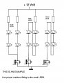
The leds are the wrong way around.
This drawing is for red and green, to see on the number of leds.
For blue you need either less leds in series or a higher powersupply-voltage.

Greetings,
Bertus
 

Thread Starter

slisgrinder

Joined Dec 7, 2008
45
yup, i am going to make sure about that, this is an example i am using to get an idea of how i am suppose to wire it to the mosfets...

[Sad realization]: oh, about the leds being backwards, i get it now... (positive to negative)
 

Attachments

Last edited:
Top