Facebook
 Google
 GitHub
 Linkedin
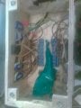
Howdy all! New year, new glitches ") All is well, tis life. I have x2 8 relay modules hooked up to an Arduino Mega. I'm using MaxMSP software to control the board. The relay modules have their own separate 5v supply.
All is well, tis life. I have x2 8 relay modules hooked up to an Arduino Mega. I'm using MaxMSP software to control the board. The relay modules have their own separate 5v supply.
The issue: I can strobe a relay very quickly for over 3 minutes without a light attached to the relay. Once I attach a light (120 V 20W T5 LED tubes) to the relay, the communication stops after 20 seconds, and then maybe comes back to life after 30 seconds. The relay contacts close at logic level low, and Ive noticed the lights are always on when stuck. I've been working with relays, Arduino and MaxMSP for well over a decade and this one is just a head scratcher.
I thought that powering the Arduino from a wall wart and then plugging into USB might help, but doesn't seem to. I'll keep sniffing around, meanwhile any help would be greatly appreciated.
All is well, tis life. I have x2 8 relay modules hooked up to an Arduino Mega. I'm using MaxMSP software to control the board. The relay modules have their own separate 5v supply.The issue: I can strobe a relay very quickly for over 3 minutes without a light attached to the relay. Once I attach a light (120 V 20W T5 LED tubes) to the relay, the communication stops after 20 seconds, and then maybe comes back to life after 30 seconds. The relay contacts close at logic level low, and Ive noticed the lights are always on when stuck. I've been working with relays, Arduino and MaxMSP for well over a decade and this one is just a head scratcher.
I thought that powering the Arduino from a wall wart and then plugging into USB might help, but doesn't seem to. I'll keep sniffing around, meanwhile any help would be greatly appreciated.