Comparing ambient temperature with desired temperature by LM35

Thread Starter

Fatih Çalış

Joined Dec 3, 2016
15
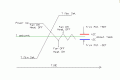
I am supposed to make a circuit which senses the ambient temperature and compares it with the desired temperature. The desired temperature is set externally by a DC voltage source and a voltage divider which has a pot. Circuit will compare these two temperature and it will run fan to decrease or stone resistor to increase the ambient temperature. But when the ambient temperature reaches the desired temperature, the circuit will enter the idle mode. In this mode, it will run neither fan nor resistor until the ambient temperature exit from the interval (desired+2C' , desired-2C'). If the ambient temperature exceed these values, the circuit will run fan or stone resistor again to reach the desired temperature and when it reaches to desired temp, it will again the enter the idle mode.
I compare the voltage value coming from LM35 with the desired value, but after this, I have no idea. Any help would be welcome :)
 

ericgibbs

Joined Jan 29, 2010
18,848
hi FC,
Have you got and read the LM35 datasheet.?
It shows a +/-10mVolt change in output voltage for a change of +/-1 degree Centigrade.

What are the required range of operating temperatures of the project.?

E
 

Thread Starter

Fatih Çalış

Joined Dec 3, 2016
15
hi FC,
Have you got and read the LM35 datasheet.?
It shows a +/-10mVolt change in output voltage for a change of +/-1 degree Centigrade.

What are the required range of operating temperatures of the project.?

E
Yes I read it, it simply gives 10mV output for every 1 Cantigrade.
Required range is from -50C' to +50C'. When the ambient temp reaches the desired one, circuit enters the idle mode and both fan and stone resistor does not work. I can do this by using two comparator. But the problematic point is, circuit will work until the desired temp and when desired temp is reached, it stops. And this is the point I have problems.
 

ericgibbs

Joined Jan 29, 2010
18,848
hi,
Look at Fig #2 on the LM35 datasheet.
The LM393 is a simple dual comparator.

Post an image showing a circuit that you have considered, we must see your work before we can help.

E
 

wayneh

Joined Sep 9, 2010
17,498
Your comparator can control only a small current, about 5mA. Your fan and heater will need much more, so you will want to control a switch with the comparator signal. There are several options for that. Do you have one in mind?

You're also going to want to control the fan and heater separately. Do you have a strategy for that?

What precision are you trying to achieve? Plus or minus 1 degree is much easier than +/- 0.1 degree.
 

Thread Starter

Fatih Çalış

Joined Dec 3, 2016
15
Your comparator can control only a small current, about 5mA. Your fan and heater will need much more, so you will want to control a switch with the comparator signal. There are several options for that. Do you have one in mind?

You're also going to want to control the fan and heater separately. Do you have a strategy for that?

What precision are you trying to achieve? Plus or minus 1 degree is much easier than +/- 0.1 degree.
Actually I'm planning to use a transistor (BD135) to increase the current to run fan or ceramic resistor. But for swtich part, I dont have any idea.
For controlling fan and heater seperately I was planning to use 2 different comparator. I drew very simply and roughly the circuit I am planning to use but I forgot to include the BD135. This circuit basically compares ambient temp with both desired +2C' and desired -2C'. But it will not work till the desired temp is reached, instead it will stop when ambient temperature enters the interval between desired -2C' and desired +2C'. And this point is the problematic part.
20161211_192236.jpg
 

wayneh

Joined Sep 9, 2010
17,498
That's getting better.

I'm not a fan of how you have established your reference voltages. You don't need the op-amp and batteries and could instead use a single resistive voltage divider with several resistors to give you the various voltages you need. You do need a stable voltage to supply the resistors.

In theory your scheme works but would be very limited by the battery voltages you can find, and by the fact that batteries lose voltage as they age.

The things you have drawn as diodes are really transistors?
 

shteii01

Joined Feb 19, 2010
4,644
That's getting better.

I'm not a fan of how you have established your reference voltages. You don't need the op-amp and batteries and could instead use a single resistive voltage divider with several resistors to give you the various voltages you need. You do need a stable voltage to supply the resistors.

In theory your scheme works but would be very limited by the battery voltages you can find, and by the fact that batteries lose voltage as they age.

The things you have drawn as diodes are really transistors?
Regarding reference voltage.
1. They said there is a pot in the voltage divider. So they already devised a method for the establishing multiple reference voltages.
2. The op amp after the voltage divider is configured as a buffer. Like you, I am not sure it is necessary. However, if they have power supplies to power it, well, it is a good thing.
 

crutschow

Joined Mar 14, 2008
34,428
the circuit does not work in this interval, as it is supposed to. But it is also needed to bring the ambient temp to the desired temp I cannot do that.
I still don't see the problem.
You design the circuit so it turns on the fan when it's more than 2 degrees above the desired temperature and turns on the heater when it's 2 degrees or more below the desired temperature.
 

Thread Starter

Fatih Çalış

Joined Dec 3, 2016
15
I still don't see the problem.
You design the circuit so it turns on the fan when it's more than 2 degrees above the desired temperature and turns on the heater when it's 2 degrees or more below the desired temperature.
This is OK but I also want to bring the ambient temp do the desired temp first. Whenever the ambient temp exits the -2 +2 interval, the circuit should bring the ambient temp to the desired temp everytime.
 

ericgibbs

Joined Jan 29, 2010
18,848
This is OK but I also want to bring the ambient temp do the desired temp first. Whenever the ambient temp exits the -2 +2 interval, the circuit should bring the ambient temp to the desired temp everytime.
hi,
You should also consider that between the +2C and -2C limits of the Tamb, that the Fan and Heater should be both OFF.
This 'deadband' is required else the circuit will be constantly switching On and Off

E
 
Top