Comparator or Microcontroller

Thread Starter

ciscoasanchez

Joined Jan 26, 2016
32
A comparator compares the voltages at it's inputs; so Va and Vb are compared with Vin.
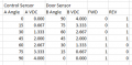
Thats what I thought. I dont think that will work. One sensor will be the controller, one sensor is the position feedback. So depending on which way motor turns depends on the controllers position relative to the sensor. I put together this logic table to think through it, maybe it will explain a little better what I am looking for. If I have a position sensor with a range of 0-90 Deg, 0.0V- 4.0V then.

A = Control Sensor B = Door Sensor
If A < B = SW1 OFF, SW2 ON
If A > B = SW1 ON, SW2 OFF
If A = B = SW1 OFF, SW2 OFF

upload_2016-1-27_8-16-55.png
 

Attachments

dl324

Joined Mar 30, 2015
16,845
You can do what you want with a derivative of the circuits you've been given. Are you up to the task or would your company be better off hiring an EE?
 

ebeowulf17

Joined Aug 12, 2014
3,307
I ran a sim of the circuit Bertus proposed. At first, it provided overlapping times when both outputs were high, instead of dead zones when both outputs were low. I added npn transistor output stages to invert the logic and it works perfectly.

dual-comparator.png

R1, R3, R5, and R6 are all 10k.
R2 is 5k, and it sets the dead-band.

I'm not sure I chose the most appropriate Linear Tech substitution for a comparator, so that may impact the specifics of this sim, but it certainly demonstrates that the schematic Bertus shared gets you most of the way there.
 

Thread Starter

ciscoasanchez

Joined Jan 26, 2016
32
I ran a sim of the circuit Bertus proposed. At first, it provided overlapping times when both outputs were high, instead of dead zones when both outputs were low. I added npn transistor output stages to invert the logic and it works perfectly.

View attachment 99520

R1, R3, R5, and R6 are all 10k.
R2 is 5k, and it sets the dead-band.

I'm not sure I chose the most appropriate Linear Tech substitution for a comparator, so that may impact the specifics of this sim, but it certainly demonstrates that the schematic Bertus shared gets you most of the way there.
You guys are awesome. I am going to start to put this together and give it a real world trial. I let you all know what happens.
 

ebeowulf17

Joined Aug 12, 2014
3,307
I think I see what happened with my sim and the logic inversion. The circuit as originally drawn used comparators with open collector outputs (active low) and my substitute comparator, chosen almost at random from the stock choices in the sim, has rail-to-rail outputs (active high.)

So I think the original would work just right as drawn, and it's just my part substitution in the sim that caused the logic inversion.
 

Thread Starter

ciscoasanchez

Joined Jan 26, 2016
32
I think I see what happened with my sim and the logic inversion. The circuit as originally drawn used comparators with open collector outputs (active low) and my substitute comparator, chosen almost at random from the stock choices in the sim, has rail-to-rail outputs (active high.)

So I think the original would work just right as drawn, and it's just my part substitution in the sim that caused the logic inversion.
Is there a good sim program I should use for this sort of thing?
 

Thread Starter

ciscoasanchez

Joined Jan 26, 2016
32
Ok, one more question, when it comes to ordering, there is a huge selection, I feel like I am not sure what to order. Any helpful tips on how to select the right part? digikey has
Are the sensors you're using independent, or do they always behave as indicated in your table?
I am not sure what you are asking, I am going to use position sensors that have an output from 0.5V to 4.5V.
 

ebeowulf17

Joined Aug 12, 2014
3,307
There are many of them to choose from, including several free ones. I use LTspice, because it's free and I saw lots of other members on this forum using it. I haven't tried any others, so I can't compare them. One obvious downside to LTspice is that it only includes Linear Technology products, although that's often not really a problem because so many parts from different suppliers are interchangeable.

If you decide to try LTspice, I can upload the .asc file for the circuit above so you can play around with it right away.
 

dl324

Joined Mar 30, 2015
16,845
I am not sure what you are asking, I am going to use position sensors that have an output from 0.5V to 4.5V.
Your table shows the sum of the two angles for the two sensors always being 90 degrees. Apparently that's not the case because you think the position of one of the sensors isn't sufficient to control both switches. Just wanted confirmation.
 

Thread Starter

ciscoasanchez

Joined Jan 26, 2016
32
Your table shows the sum of the two angles for the two sensors always being 90 degrees. Apparently that's not the case because you think the position of one of the sensors isn't sufficient to control both switches. Just wanted confirmation.
You are correct, the sum of the two angles will not be 90, those values were just an example.
 

Thread Starter

ciscoasanchez

Joined Jan 26, 2016
32
I have successfully built a working simulator with a different comparator that has a wider range of input voltages, now to build and test it. Thanks again for all the help, I feel a bit like a cheater, but I learned a lot.
 

bertus

Joined Apr 5, 2008
22,270
Hello,

You are smart by asking.
Did you read my signature?

When you do ask questions, you may look stupid.
When you do NOT ask questions, you will STAY stupid.
Now you have a possible solution for your problem.

Bertus
 

ebeowulf17

Joined Aug 12, 2014
3,307
I have successfully built a working simulator with a different comparator that has a wider range of input voltages, now to build and test it. Thanks again for all the help, I feel a bit like a cheater, but I learned a lot.
This is nothing at all like cheating. You got some help brainstorming a solution, and now you're going to work on the implementation. You're learning in the process. This is all good. Hopefully you'll report back on the results once you've done some experimenting, and others can learn from your experience.
 

Thread Starter

ciscoasanchez

Joined Jan 26, 2016
32
I have good news, I successfully built the circuit. It works, it turns on and off as expected. I have a new problem, I am trying to connect to the existing amp. I just realized the amp needs a (-) signal not a (+). is there a good way to switch polarity of the output?
 

ebeowulf17

Joined Aug 12, 2014
3,307
When you say it needs a negative signal, do you mean negative voltage with respect to ground, or that you need to switch one of its pins to ground to activate it as opposed to sending it a positive voltage?

If it's the former, you need a source of negative voltage. If it's the latter you just need a simple logic inversion, which can be accomplished with npn transistors, n-channel MOSFETs, etc. My example circuit in an earlier post uses npn transistors and pull up resistors to reverse the logic of the op amp outputs. You could do something similar.
 
Top