Facebook
 Google
 GitHub
 Linkedin
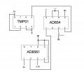
I've been attempting to get a temperature sensor (TMP01) hooked up and reporting to a Raspberry Pi as part of a project. As far as I can tell the temperature sensor works fine, and the voltage-to-frequency converter (AD654) I have it hooked into works...almost as well as the temperature sensor does. The main problem I have with it is that it outputs 2.8V on a low signal, and 3.5V on a high signal which, being a digital device, both register as "on" by the pi.
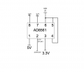
My solution was to use a 3.3V pin on the pi as a reference point for a comparator (AD8561) to compare the converter's output with and output a proper high and low voltage that the pi will have no trouble recognizing. However, the comparator doesn't seem to be acting the way I expected it to.
From the attached image you can see what I've measured going in and out from the pins on the comparator, as well as what I've measured coming from the converter and pi on the wires. I'm having trouble determining what the problem could be, let alone what I should do to solve it. I've had a friend of mine walk me through a few things to try and troubleshoot it, but he wasn't able to make heads or tails of what's going on with it. One of the things we tried was grounding out both inputs and found that the outputs weren't the same, shouldn't they be?
Any suggestion as to what might be going on with the comparator, or another potential solution that hopefully doesn't involve slapping an Arduino in the middle to act as the voltage-to-frequency converter, would be quite appreciated.
Attachments
-
 14.3 KB Views: 17