Facebook
 Google
 GitHub
 Linkedin
Good Morning.
Please I need help to know how to design a common mode filter.
I don't know how to proceed.
The mechanical chassis and the ground reference are isolated.
I have DCDC which have a decoupling frequency of 500Khz.
I have previously design a differential mode filter with a cut-off frequency of 12KHz.
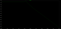
I have to respect the current limit constraint of :
- 80 dBµA up to 100KHz
- Decrease of 20dB by decade from 100KHz tto 10MHz
- 40 dBµA from 10MHz and upper
I have read that a two order filter with a commode mode filter and capacitors connected to the mechanical chassis should be enough.
But how to select both component values ? How to simulate thanks to LTspice (attached file) ?
Thanks per advance for your help !

Please I need help to know how to design a common mode filter.
I don't know how to proceed.
The mechanical chassis and the ground reference are isolated.
I have DCDC which have a decoupling frequency of 500Khz.
I have previously design a differential mode filter with a cut-off frequency of 12KHz.
I have to respect the current limit constraint of :
- 80 dBµA up to 100KHz
- Decrease of 20dB by decade from 100KHz tto 10MHz
- 40 dBµA from 10MHz and upper
I have read that a two order filter with a commode mode filter and capacitors connected to the mechanical chassis should be enough.
But how to select both component values ? How to simulate thanks to LTspice (attached file) ?
Thanks per advance for your help !
Attachments
-
2 KB Views: 2
Last edited by a moderator: