COMMON MODE EMI FILTER

Thread Starter

ElectronicNewbie0

Joined Oct 18, 2025
54
Hello all,

I started to build a power supply, to start using a bit the basic components and so on,

what im trying to build is a power supply 24V/4A, the blocks that i had in my mind were: a common mode choke emi filter, a transformer, a bridge rectifier and then 4 transistors that will split up that 4A current, so each one will have to handle 1A ( its something that i chose ) then a circuit of driving for the base of the transistors, to regulate the voltage at 24V fixed.

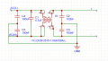
With that said, now i started building the first block, which is the common mode filter.

I have looked for some designs online and took example from them.

I have chose a common choke inductor that can handle 30A ( so im really above that 4A requirement ), with an inductance of 1mH, also i chose a capacitor of 4.7uH, which i calculated to have a frequency cut of fc= 1/ 2π√(LC)=2.33kHz
So this means i will cut all the harmonics at high frequency.

is this designffine? what u suggest me to add or change?

thanks for all.
 

Attachments

Hymie

Joined Mar 30, 2018
1,347
Such a common mode filter arrangement is commonly used in switch mode power supplies (at the mains input), but not in linear supplies. It's normal to see any required filtering applied at the dc secondary output, in linear supplies.
 

Ian0

Joined Aug 7, 2020
13,097
You can certainly include it, but it won’t be anywhere near as effective at removing common mode noise as the transformer, especially if you use a split bobbin transformer.
Generally select for the highest inductance available for the size. 30A current rating is overkill, and you are losing out on inductance.
4.7uF is a rather large capacitor to have on the input, you will probably find that your mains plug contacts get well cleaned when you plug it in!
 

Thread Starter

ElectronicNewbie0

Joined Oct 18, 2025
54
You can certainly include it, but it won’t be anywhere near as effective at removing common mode noise as the transformer, especially if you use a split bobbin transformer.
Generally select for the highest inductance available for the size. 30A current rating is overkill, and you are losing out on inductance.
4.7uF is a rather large capacitor to have on the input, you will probably find that your mains plug contacts get well cleaned when you plug it in!
I saw different design, where they select this value as input capacitance, how can i understand which value is the best in my case?
For the inductance so i look for a lower current, like 6A, so i gain in inductance
 

Thread Starter

ElectronicNewbie0

Joined Oct 18, 2025
54
You can certainly include it, but it won’t be anywhere near as effective at removing common mode noise as the transformer, especially if you use a split bobbin transformer.
Generally select for the highest inductance available for the size. 30A current rating is overkill, and you are losing out on inductance.
4.7uF is a rather large capacitor to have on the input, you will probably find that your mains plug contacts get well cleaned when you plug it in!
I was thinking about adding a NTC Resistor in series in the input, so i limit the inrush current?

NTC Thermistor Inrush Current Limiter 8 Ohm 6A ICL20 - AMWEI Thermistor Sensor
like this one?
 

MisterBill2

Joined Jan 23, 2018
27,159
Hymie is totally correct in post #2. A "classic" transformer step-down supply does not produce all if that switching noise that the filter shown is intended to keep out of the supply connection.
Inrush current protection in a capacitor input supply certainly is a consideration, and there are a variety of ways to achieve it. An NTC series resistor can be effective but it does reduce the efficiency, because that resistor will continue turning power into heat after the startup.
Since the supply will be regulated and you specify FOUR regulator transistors, and I am assuming that there would be a filter capacitor before the regulators, simply selecting a bridge rectifier with a surge current rating adequate for the inrush will be the simplest choice, and a conservative approach.
There are additional considerations, however. It is seldom a requirement to have all of the filtering done prior to the regulator, because a regulator with adequate response time will remove most of the supply ripple voltage, if it's input voltage margin is adequate. That can allow a cost reduction on the input filter. The consequence is a greater requirement for the filtering of the regulator reference and operating voltage. But that is a much lower current and so the filtering is simpler and cheaper.
Additional filtering done after the regulator is less demanding. You will need to include emitter series equalizing resistors for the pass transistors, which will also tend to reduce the output filter inrush current a bit.
 

Thread Starter

ElectronicNewbie0

Joined Oct 18, 2025
54
Hymie is totally correct in post #2. A "classic" transformer step-down supply does not produce all if that switching noise that the filter shown is intended to keep out of the supply connection.
Inrush current protection in a capacitor input supply certainly is a consideration, and there are a variety of ways to achieve it. An NTC series resistor can be effective but it does reduce the efficiency, because that resistor will continue turning power into heat after the startup.
Since the supply will be regulated and you specify FOUR regulator transistors, and I am assuming that there would be a filter capacitor before the regulators, simply selecting a bridge rectifier with a surge current rating adequate for the inrush will be the simplest choice, and a conservative approach.
There are additional considerations, however. It is seldom a requirement to have all of the filtering done prior to the regulator, because a regulator with adequate response time will remove most of the supply ripple voltage, if it's input voltage margin is adequate. That can allow a cost reduction on the input filter. The consequence is a greater requirement for the filtering of the regulator reference and operating voltage. But that is a much lower current and so the filtering is simpler and cheaper.
Additional filtering done after the regulator is less demanding. You will need to include emitter series equalizing resistors for the pass transistors, which will also tend to reduce the output filter inrush current a bit.
Ok alright, thanks for the response, yeah i understood that thing, i still wanted to make the EMI filter for design/learning purposes, im taking example from other schematics now.
 

MisterBill2

Joined Jan 23, 2018
27,159
Please let us know as to what type of supply you have selected.
And be aware that switching mode supplies are much more challenging to design.
 

MrChips

Joined Oct 2, 2009
34,627
If you want to include an RF line filter in your power supply project, you can buy ready made modules that are easy to install.
Check out filters from TE Connectivity Corcom filters, Qualtek, XP Power, etc.

1764088022759.png


I prefer to use a panel mount socket that kills two birds at once. You can also get one that includes the fuse holder (and even the power switch).

1764088187572.png
 

MisterBill2

Joined Jan 23, 2018
27,159
When using the in-line filter it is often important to have it close to the power entry point, so that incoming noise does not radiate from the long connection lead length. This is most important in systems with high levels of RF in the area.
 
Top