You have the emitter grounded and the bias point set to 0.68 Volts. The Q-point is very close to cutoff and the transistor AC gain is different for the positive and negative peaks. For proper AC operation the Q-point should be at or near Vcc/2. You need to add an emitter resistor and a bypass capacitor.
I don't know, I don't have an intimate knowledge of abbreviated models. I can tell you that having no emitter resistor and setting the Q-point to almost exactly the maximum Vbe of an NPN transistor is going to make one terrifically crappy amplifier in terms of distortion. Make the the input bigger and you will see clipping -- BIG TIME.
I'm not gonna discuss the scheme. I will explain the asymmetric amplification of positive and negative half-wave signal. The bigger the signal, the more asymmetry. If the signal is 1 mV, you will hardly notice any asymmetry. The gain of the transistor depends on the current. S=1/re=ie/26mV. Higher current, higher gain. At 10 mV, the harmonic factor is approximately 10%. At the signal peak, the transistor carries a higher current and a correspondingly higher voltage gain.
Because you forgot that the BJT is a very nonlinear device. And that the voltage gain is not constant but will change with the input signal exponentially.
Av = Vout/Vin = - (Rc * Is)/Vt * exp^(Vin/Vt) (with CE capacitor across RE ressitor)
You can improve the distortion by adding external emitter degeneration resistor (without CE capacitor).
But to get "low THD" you need to pick RE >> re.
Why do you have two different schematics? One has the base bias resistor values both at 711k which is way too high.
Why is your input signal level so low at only 1mV peak? A microphone averages 7mV and has peaks to 20mV or more.
Why is the transistor biased so that it is almost cutoff?
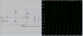
Why is your timebase so wide that it is showing only very narrow waveforms?
Your transistor has a squashed top part near cutoff and a more normal lower part near saturation because its gain is less near cutoff and it is missing some negative feedback.
If you bias the transistor halfway between cutoff and saturation then the output level can be much higher before clipping.
You should also look at the DC voltages at the collector of the transistor like in my simulation.
If you need high gain then use two or three transistors, each with some negative feedback.
I have biased the transistor normally but since it has no negative feedback it still has severe distortion with an input of 20mV peak.
Why do you have two different schematics? One has the base bias resistor values both at 711k which is way too high.
Why is your input signal level so low at only 1mV peak? A microphone averages 7mV and has peaks to 20mV or more.
Why is the transistor biased so that it is almost cutoff?
Why is your timebase so wide that it is showing only very narrow waveforms?
1) my bad: the 711k schematic wasn't meant to be uploaded. I wanted to share the image schematic.
2) it's just an exercise done to familiarize myself with CE ampli
3) I was experimenting different OPs
4) There is no particular reason behind this choice.
If your aim is to minimize distortion then you should do two things:
1) choose moderate gain per stage,
2) use negative feedback.
You can achieve both of these easily by inserting a resistor RE in the leg of the emitter.
For example, if you choose the load resistor Rc = 2.2kΩ, then RE= 220Ω would give a gain of Rc / RE = 10.
Your simulation has no question about theory on it.
The collector of the transistor is biased wrongly at 4.3V so it is almost cutoff. I changed the value of your resistor R2 from 6579 ohms to 10k ohms and the gain with a 20mV peak input increased 3 times and the distortion became less.
Another problem with your circuit is that since each transistor has a different amount of beta (DC current gain, even if they have the same part number) then transistors with a high beta will be saturated and transistors with a low beta will be cutoff. Adding an emitter resistor will add DC feedback to reduce this effect and if the emitter resistor is unbypassed then there will be negative AC feedback to reduce the distortion and gain.
Hi all
Can you please tell me why I get increased NPN transistor collector voltage when I decrease the resistor value in the current mirror?
When I decrease that value the current mirror can give more current to the NPN transistor but I cannot understand why my OP voltage increases.
Cheers
I found my last post merged into this thread even if it's related to another circuit (I created a new thread for it).
I hope it will not go unnoticed and someone will answer my new question.
yeah I can see that from the values in the simulator... but why does it happen? Do I have to see the current mirror as its ouput equivalent resistor? Doesn't that equivalent ouput resistor value decrease when the output current increases? I'm confused.
A thought experiment... suppose the PNP wants to make 2mA flow but the NPN wants 1mA to flow. Which one will win?
So there's 2mA pulling "up" and 1mA pulling "down" then what does the voltage on Vout do?
 Facebook
 Google
 GitHub
 Linkedin
 48.7 KB Views: 39


")


