Common Emitter Transistor Analysis

Thread Starter

Schoppy

Joined Jul 7, 2014
26
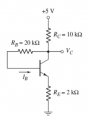
Hey guys, I can't seem to figure this one out. My issue with this one is how the solution converted Ic immediately to Ie. I understand that while analyzing the common emitter that as long as you have a emitter resistance that is relatively close to the collector resistance then Ic = Ie but where exactly is Ic located? It's my understanding that it is the current that is entering the transistor. In this case we have the Vc node connected to Rb. When I solved the problem I set the current passing through Rc as I1 and then set I1 = Ib + Ic. Then converted everything into Ib using the beta conversion then solved for Ib and solved the rest of the problem that way. Any help is appreciated!!
 

Attachments

Thread Starter

Schoppy

Joined Jul 7, 2014
26
And now I realize that Ic does not depend on Beta so my thinking of converting Ic to Ib using Beta is invalid. I still could use Ic = Ie and then set I1 = Ib + Ie and solve that way but according to the solution Ic is the current passing through the resistor, not the current entering into the transistor? I'm so confused right now lol
 

WBahn

Joined Mar 31, 2012
30,052
As long as the transistor is not in saturation, then for most purposes you can assume that Ic ~= Ie (unless the active-region beta is particularly low, which can be the case with some power transistors).
 

WBahn

Joined Mar 31, 2012
30,052
I'm confused, too. Is the solution you posted in the first post YOUR solution, or the "official" solution?

That solution appears to use a beta of 75. Where did that magic number come from?

What do you get if you assume that beta is infinite? How close is that to when you assume beta is 75? Are they close enough so as not to matter? If so, then the circuit is independent of beta.

At some level, the behavior will always depend on beta -- a circuit that is said to be independent of beta merely means that the effect of beta is negligible compared to what is acceptable.

For this circuit, I get a difference of about 5%. Is that "close enough"? Very possibly. With resistors that are such nice round values, the likelihood is very high that 5% is good enough.
 

Thread Starter

Schoppy

Joined Jul 7, 2014
26
Yes in the original problem it had beta as 75. But I've come to the acceptance of Ie = Ic, I just have t come to the conclusion as to exactly where Ic is. I had assumed it was the current entering the transistor. In the solution they have Ic as the current passing along Rc, when I did the problem I had the current that was passing along Rc labeled as I1 which the hen splits when it hits the node of Vc where Ib goes along the route of Rb and Ic enters the transistor. So I can't seem to figure out why Ic is the current that passes along Rc and not the current that enters the transistor.
 

WBahn

Joined Mar 31, 2012
30,052
Yes in the original problem it had beta as 75. But I've come to the acceptance of Ie = Ic, I just have t come to the conclusion as to exactly where Ic is. I had assumed it was the current entering the transistor. In the solution they have Ic as the current passing along Rc, when I did the problem I had the current that was passing along Rc labeled as I1 which the hen splits when it hits the node of Vc where Ib goes along the route of Rb and Ic enters the transistor. So I can't seem to figure out why Ic is the current that passes along Rc and not the current that enters the transistor.
Ic is, by definition, the current flowing into the collector pin of the transistor. I still don't know if the "answer" you presented is YOUR answer or THEIR answer. You say that your answer used I1 as the current in Rc and you say that their answer used Ic as that current. But the answer you presented doesn't do either of those -- it uses Ie, which is correct.
 

Thread Starter

Schoppy

Joined Jul 7, 2014
26
Ok my appologies. The solution I posted was the books solution. In the picture here I have how the book has Ic in the top picture and what I originally assumed Ic would be in the bottom picture. I feel like I am right but I'm still new to transistors and just need some clarification. Thanks again!

Moderators note: Please keep the size of images smaller, I cropped and resized the image
 

Attachments

Last edited by a moderator:

Thread Starter

Schoppy

Joined Jul 7, 2014
26
In the books solution they set Ic = Ie immediately and don't declare it(for the top picture).
 
Last edited:

WBahn

Joined Mar 31, 2012
30,052
Ok my appologies. The solution I posted was the books solution. In the picture here I have how the book has Ic in the top picture and what I originally assumed Ic would be in the bottom picture. I feel like I am right but I'm still new to transistors and just need some clarification. Thanks again!

Moderators note: Please keep the size of images smaller, I cropped and resized the image
In the books solution they set Ic = Ie immediately and don't declare it(for the top picture).
Actually, the book's solution (which is correct) does NOT set Ic=Ie and it does NOT have Ic being the current in Rc. Look at the equation

answer.png
and you will see that the current that is multiplied by Rc (the 2kΩ resistor) is Ie and not Ic.

The top left equation is more properly set up as

\(
Vcc = I_E R_E \; + \; V_{BE} \; + \; I_B R_B \; + \; \( I_C+I_B \)R_C
\)

To this you know that

\(
I_C \; = \; \beta I_B
I_E \; = \; I_C \; + \; I_B
\)

Combining these two you get

\(
I_B \; = \; \frac{I_E}{\beta + 1}
\)

Applying this to the original equation to eliminate Ic and Ib, you get:

\(
Vcc = I_E R_E \; + \; V_{BE} \; + \;\frac{I_E}{\beta + 1} R_B \; + \; I_E R_C
\)
 

Thread Starter

Schoppy

Joined Jul 7, 2014
26
Ok now that makes sense, I don't know why I was under the impression that when there is a emitter resister on a common emitter transistor then Ie = Ic. That's where I screwed up. Thank you for clearing that up!!
 

WBahn

Joined Mar 31, 2012
30,052
Ok now that makes sense, I don't know why I was under the impression that when there is a emitter resister on a common emitter transistor then Ie = Ic. That's where I screwed up. Thank you for clearing that up!!
Good, glad that helped.

There's no magic here. You have a box with three terminals marked C, B, and E. The currents are defined such that Ic and Ib flow into the box and Ie flows out of the box. From that, you know that KCL dictates that Ie = Ic + Ib. It doesn't matter what is in the box. Now, if you know that Ic is very large compared to Ib, then you can say that Ic is about equal to Ie and, for most purposes, treat them as being the same. In that same breath, you are saying that Ib is about equal to zero and, for most purposes, can treated it as being zero (at least relatively speaking).

Let's see what that results in in this case.

\(
V_{CC} \; = \; I_E R_E \; + \; V_{BE} \; + \; I_B R_B \; + \; \( I_C+I_B \)R_C
\)

The then becomes:

\(
V_{CC} \; = \; I_E R_E \; + \; V_{BE} \; + \; I_E R_C
\)

So

\(
I_E \; = \; \frac{\( V_{CC}\; - \; V_{BE} \)}{R_C \; + \; R_E}
\)

And then we have

\(
V_C \; = \; V_{CC} \; - \; I_E R_C
\)

which yields

\(
V_C \; = \; \( V_{CC}\; - \; V_{BE} \)\frac{R_E}{R_C \; + \; R_E}\; + \; V_{BE}
\)

which simplies to

\(
V_C \; = \; \frac{\( V_{CC}R_E\; + \; V_{BE}R_C \)}{R_E \; + \; R_C}
\)

Notice how, up to this point, I haven't used any actual values. This let's me do a number of sanity checks to see if this result seems reasonable and it also let's me track down any errors and fix them much more easily. Not to mention that I can quickly update my results if I change one of the component values.

Now we will plug in the results:

\(
V_C \; = \; \text{\frac{\(5V \cdot 2k\Omega\; + \; 0.7V \cdot 10k\Omega \)}{2k\Omega \; + \; 10k\Omega}}
\;
V_C \; = \; \text{\frac{\(10V \; + \; 7V \)}{12} \; = \; 1.417 V}
\)

Keep in mind that this is an approximation, namely that Ic=Ie which is the same as saying that we are assuming that beta is infinite. This assumption results in a voltage that is within 5% of the value we calculated using a beta value of 75.
 
Top