common emitter amp output distorted, can't figure out why, need help please

Audioguru

Joined Dec 20, 2007
11,248
How exactly does shorting out Re to the ac signal do this? Don't you want to short out Re so that the ac signal does not disturb Ve and thus Vbe and thus keep the transistor at the operating point? Thats why you do this I thought.
The voltage gain of a common-emitter transistor is RC/RE where RC is the collector resistor in parallel with the load and RE is the unbypassed emitter in series with the internal emitter resistance (26/emitter current in mA).
bypassing Re makes it an AC short circuit so RC/RE is a high number and the voltage gain is high.
The emitter voltage does not change.

I know the signal is a voltage but all voltages cause current.
Changing the voltage across the base-emitter diode changes its current logarithmically which is non-linear (distortion). If you feed the base with a current signal instead of a voltage signal then your curve tracer shows that the collector current is very linear for low distortion.

So the input voltage causes a proportional current that looks the same as the voltage but is divided by the resistors.
No.
The base resistors are for DC biasing of the operating point. The signal is not divided by the base resistors.

So doesn't the transistor actually amplify that current? That is ib(t) which was caused by Vbe(t)?
Yes, but the base-emitter is a diode that has a logarithmic current response to a voltage input that causes severe distortion at a low current.

We were taught by Sedra and Smith book that Re = Vt/ie where Vt = 25mv (thermal voltage). Might you be referring to the same thing?
Yes, they are the same. I was taught 26 and you were taught 25.
 

Audioguru

Joined Dec 20, 2007
11,248
is the OP simulation a software ckt or an actual practical application.
The OP built the circuit and tested it with a curve tracer, a signal generator and an oscilloscope. My simulation produced the same results.

if later the case then anyone ever thought of the ESR of the caps he is using?
The emitter current is 5ma so the internal emitter resistance of the transistor is 26/5= 5.2 ohms which is in series with the ESR of the capacitor. If the emitter capacitor has an ESR as high as 0.52 ohms then there will be a slight reduction of voltage gain.
The ESR of the input and output capacitors must be many kil-ohms to make any difference.
 

Audioguru

Joined Dec 20, 2007
11,248
I understand what Ce is for now. But there is a small typo in the ebook. Here....
Nice catch. I never read the ebook.

Did you notice that opamps have an extremely high voltage gain and an extremely low distortion but do not use emitter resistor bypass capacitors?
 

hobbyist

Joined Aug 10, 2008
892
I have some questions regarding this problem as well.

I'm getting around 7mA. ICQ.
actual measurements put VC at around 7v. very close to it.

Loking at count volta's first schem.
It looks like he is only getting around 5.2mA. ICQ. (assuming vbe = 0.7)
That puts his VC at around 8.78v.
So first he is higher on the load line.

I was able to attain 5v p-p with the load and using 14v. supply.

So if I was able to reduce the distortion using the same VCC, then most of his problem would be where he was sitting at on the load line during quiescent period.

I realize he said he was close to design values, I don't doubt that, but according to the math his Q point is at 8.78v.


Now I designed the same circuit criteria, with a 8v. supply.

I got around 4.02v. for my Q point. base and emitter voltages right on spec. with calc.
When I applied a signal I got good neg. peeks, down to around -2.8v. but the positive peeks, flattened out at 2v.

As I was looking over the schem. I began to analyse something that I would like you guys to comment on,

First. I am getting good neg. peeks, at spec. values, due to the transistor supplying enough current to drop its VC. which in turn sends the signal to the load through the capacitor.

BUT. when the input goes neg. (the input NON distorted, due to high input Zin), the transitor is driven towards cutoff, to reduce its current as it should, so that VC will increase as it should,

HOWEVER, the Coupling capacitor, is still holding a charge on the collector terminal, AND must discharge through RC,
heres the point I'm trying to make, If RC is too large with respect to the :LOAD, then the discharge of the coupling capacitor will produce a voltage drop across RC enough to keep the voltage on the load side hindered from reaching it's max potential due to the drop already on RC ??

If RC is made much lower than load, then the voltage drop will be less with respect to the drop across the load ??

The reason I was able to get a fairly decent waveform using 14v. for the first schem. was because I had enough voltage at the Q point with respect to the amount of AC impressed upon it. ??

Just my theory:::::

Count Volta:

I just changed the RC from 1K to 200 ohms.
Then rebiased the stage to give VC of 4v. for the same 8v. supply.

Now I have the 5v. P-P with NO distortion, on the waveform.

So it looks like from these experiments, that for a given Vout (P-P) then a high enough supply needs to be used when the RC value is high with respect to the load, in order to obtain the voltage swing, on the positive peek, with no distortion.

When using a low supply voltage with respect to the Vout (P-P) then it is best to make the RC value as low as possible with respect to the load, for the positive peeks to be realized.

Hope this helps clear some of your confusion up.

I know it cleared a lot of it up for me...

As you can see learning this stuff is an ongoing process.
I've been in this hobby since 1980, and I'm just now starting to understand this better.

Mainly from the help of this forum...
 
Last edited:

Audioguru

Joined Dec 20, 2007
11,248
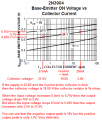
The Q point depends on the hFE and Vbe of the transistor. I calculated 9.08V. The collector current is 5mA and the Vbe of a 2N3904 transistor at a collector current of 5mA is 0.73V.

The RC and the coupling capacitor to the load does not cause the distortion because the same distortion is also present with no load.

Your waveform was not too distorted because your emitter capacitor had a low value so the gain was low and the negative feedback was high.

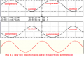
Here is another look at how a voltage signal input to the base-emitter diode of a transistor produces a distorted logarithmic output swing. The Q-point is 4mA. I feed a low distortion signal of 50mV peak.

When the input goes 50mV positive the output changes from a Q-point of 4mA to 20mA when the transistor conducts.
But when the base voltage goes 50mV negative the collector current is not cutoff as you think it should be. So the top portion of the waveform is severely compressed, not clipped.

EDIT: Change 0.5mV to 50mV on my chart description.
 

Attachments

Last edited:

Thread Starter

count_volta

Joined Feb 4, 2009
435
Problem solved....

I halved my input ac voltage with a voltage divider (because the function generator only goes as low as 50mv peak) and viola.

The TA explained what was going on. I will try to say what he said. First here is my oscilloscope screenshot.


This is without the 1kΩ load, in other words this screenshot is showing the output voltage being taken between Cc2 and ground.

No distortion, and almost 5V PP output. Well 4.18V. Later I will say what I did to increase it to 5v PP. The input is now 42mv PP.

Please read every word of the post by the way!!!

Sorry that I have to do this but sadly I noticed that many people don't read what people write in posts but just skim through it. This is BAD. Please read every word.

So to explain what was going on earlier (according to the TA) and it makes sense to me.

This is the oscilloscope screenshot I posted earlier with the distortion again.


This is my operating point and characteristics again.


So here I go explaining. Look at the oscope screenshot. The input and output are 180 degrees out of phase. The distortion occurs when the input is on the lower half of the swing.

Now look at the characteristics. The lower half of the swing on the input corresponds to everything to the right of the Q point. So its from Vce = 7V to Vce = 12V. This is close to the cutoff region on the right there.

When the ac input was 100mv PP, what happened is it made Vce go way beyond 12V, and into the cutoff region. The cutoff region is not linear (as audioguru said), and hence the clipping.

Now when I decreased the input ac voltage, the highest that Vce ever gets is approximately 12V, or at least its still in the active region where everything is linear.

So as you decrease the input ac signal, the distortion stops.

Now the next part of my lab experiment asked this.

5.) Measure the maximum undistorted swing in the output voltage and record it in your lab report. Is it less than the 5Vp-p that you designed for? If yes, mention some of the reasons that lead to this reduction in output voltage.

6.) To correct the problem and obtain 5Vp-poutput you have different options. One such option is to increase the value of the power supply VCC while maintaining all other components in the circuit at their present values. Record the value of VCC that restores the output voltage to 5V p-p.


As you can see the answer to question 5 is yes. The max voltage swing is 4.18 V PP.


So I increased Vcc without changing anything else like question 6 says. At Vcc= 17V I got a voltage swing of 4.938V PP.


So increasing VCC actually tilted the load line and moved the Q point to about Vce = 8V.


Here is a screenshot showing the oscilloscope with Vcc=17V. Again this is without the 1k load resistor. Its with the output being taken between Cc2 and ground.


Hobbyist this is more or less the same thing you did. Instead of changing the resistor values, I increased Vcc which moved the operating point to Vce = 8V.

If you guys have questions please ask me. I consider this as a solution to my problem. Thanks for all the help.

Now if anyone remembers the thread I started last summer about amplifying my voice with a class A BJT amp (it was like 40 pages LOL), this pretty much answered my original question. Here I am getting an ac voltage gain of about 100. Now if my voice is like μV, in theory maybe this should amplify it to audible range. I just have to try now!!!

What I learned from this is, you design an amplifier to do one thing, you hook it up and look at the results. Then you see some problems and you adjust for them until there is no distortion and correct amplification. Now that is science, not taking resistor values out of your head. Our profession is science not magic. (Mostly). ;)
 
Last edited:

ifixit

Joined Nov 20, 2008
652
Hi,

I hate to nit-pick, but your signal is still distorted. The top is more rounded than the bottom. You would notice if it was your favourite tune.

The eBook seems to suggest that the value for Re be; 'picked out of a hat'. I.E. Re = 10% to 50% of Rc. e.g. 1KΩ / 10 = 100Ω for Re.

How did you arrive at your value of 510Ω? 50% of Rc? Try 27%.

A better value is one that minimizes distortion and compensates for the effects of temperature on; the BE junction, and Iceo. As temperature increases the Vbe will decrease by ~2mV/°C. This increases Ib and therefore Ic. The increase in Ic causes more voltage drop across Re which tends to compensate for the temperature effect... if you get the value of Re right.

Who likes to do simultaneous equations? Not me. I pick from the hat and use a simulator:).

Have Fun,
Ifixit
 

Thread Starter

count_volta

Joined Feb 4, 2009
435
Hi,

I hate to nit-pick, but your signal is still distorted. The top is more rounded than the bottom. You would notice if it was your favourite tune.

The eBook seems to suggest that the value for Re be; 'picked out of a hat'. I.E. Re = 10% to 50% of Rc. e.g. 1KΩ / 10 = 100Ω for Re.

How did you arrive at your value of 510Ω? 50% of Rc? Try 27%.

A better value is one that minimizes distortion and compensates for the effects of temperature on; the BE junction, and Iceo. As temperature increases the Vbe will decrease by ~2mV/°C. This increases Ib and therefore Ic. The increase in Ic causes more voltage drop across Re which tends to compensate for the temperature effect... if you get the value of Re right.

Who likes to do simultaneous equations? Not me. I pick from the hat and use a simulator:).

Have Fun,
Ifixit
Hmm you may be right. I'm sure there is a way to know if your signal is distorted or not. But for the purposes of this lab, they want us to learn how to design a good CE amp with a high gain and a mostly undistorted signal.

The nitpicking about distortion will occur when I take more advanced electronics courses later.

I got Re because I know ic and ib from the transistor curve tracer characteristics (roughly) and then ie = ib+ic. They also gave us this equation. Ve = 0.2*Vcc. Not sure where they got it from. So knowing these two facts I solved for Re. Does anyone know where they got that relation for Ve? Look familiar?
 

Audioguru

Joined Dec 20, 2007
11,248
I agree that the waveform is still very distorted. I can see it from experience but a new person might see the distortion if the waveform is compared when it is shown upside-down and also when a low distortion sine-wave is shown.
The waveform is not symmetrical.

Preamps and audio opamps have distortion that is barely measurable at 0.00008%.
Before with a higher level this transistor had distortion of about 40%. Now with its input level reduced its distortion is about 15% which still sounds awful.
 

Attachments

Thread Starter

count_volta

Joined Feb 4, 2009
435
Audioguru I have some questions for you.

First, the output of a microphone, is it a voltage or a current? I would think voltage since what is happening is your voice acts like a mini generator that generates ac voltage.

Also, what is the usual output in volts or amps of a microphone? This is without an amplifier. Like micro volts or even less?

I think you see where I'm going with this. Now that I learned the basic theory I can go back and try my audio, class A amp again. Will it work, don't know. But I gotta try. My ac gain was around 100. Sounds like a lot. Maybe.
 

hobbyist

Joined Aug 10, 2008
892
The Q point depends on the hFE and Vbe of the transistor.

Here is another look at how a voltage signal input to the base-emitter diode of a transistor produces a distorted logarithmic output swing. .
Thanks for the great explanation,
I understand that chart better now,
looks like using that chart, one can determine the available output swing, for a given input , and determine the best place to set the collector current, for low distortion possible.
 

Audioguru

Joined Dec 20, 2007
11,248
Audioguru I have some questions for you.

First, the output of a microphone, is it a voltage or a current? I would think voltage since what is happening is your voice acts like a mini generator that generates ac voltage.

Also, what is the usual output in volts or amps of a microphone? This is without an amplifier. Like micro volts or even less?
A dynamic mic has a coil and magnet like a mini speaker. It generates a voltage.
An electret mic is a "condenser" that uses a vibrating thin film near a metal frontplate and backplate making a variable capacitor voltage divider. 48V is permanently stored in the electret material biasing the backplate at 48V. The "condenser" is extremely high impedance so a Jfet source-follower is used to reduce its output impedance. The Jfet must be powered.

Both mics produce 5mV to 10mV when you talk at a normal loudness about 10cm away.
 

Thread Starter

count_volta

Joined Feb 4, 2009
435
It sounds like a dynamic mic input might be amplified by the amplifier I built, if I change the characteristics a bit and remove the distortion. It had an ac gain of 100. 10mv*100 =1V. Maybe. Am I right?
 

Audioguru

Joined Dec 20, 2007
11,248
It sounds like a dynamic mic input might be amplified by the amplifier I built, if I change the characteristics a bit and remove the distortion. It had an ac gain of 100. 10mv*100 =1V. Maybe. Am I right?
Then when you turn it on you will have acoustical feedback howling because the sound from the speaker will be picked up by the mic and amplified and it goes around and around.
 

hobbyist

Joined Aug 10, 2008
892
Audioguru

I think you see where I'm going with this. Now that I learned the basic theory I can go back and try my audio, class A amp again. Will it work, don't know. But I gotta try. My ac gain was around 100. Sounds like a lot. Maybe.
Remember your amp you just designed is working into a 1K ohm load.

If you are designing for an audio class A amp with a speaker, then you have a whole new redesign to get proper matching of your output impedance to the load.
 

Audioguru

Joined Dec 20, 2007
11,248
.....to get proper matching of your output impedance to the load.
Most audio circuits never match the impedances. If you do, then you throw away half the signal voltage and then a power amplifier cannot damp the resonances of speakers.

A 150 ohm dynamic mic feeds a preamp with an input impedance of 1k ohms or 2k ohms.

The opamp output of a preamp is 0.04 ohms to 100 ohms and feeds a power amp with an input impedance of 10k to 100k ohms.

The speaker is 8 ohms but the output impedance of the power amplifier is 0.04 ohms or less.
 

Audioguru

Joined Dec 20, 2007
11,248
Do real sound amps have something to prevent acoustic feedback then?
There are "feedback eliminator" circuits that simply detect the frequency of feedback and reduce the gain at that frequency with a notch filter but they do not work well.

One time I used a "frequency shifter" that helped reduce feedback a little and sounded strange.

Most people just turn down the gain and have the people speaking or singing to "eat the mic".
 

retched

Joined Dec 5, 2009
5,207
Most people just turn down the gain and have the people speaking or singing to "eat the mic".
Yummm.. I remember those days.. It is amazing what you will find on a mic windscreen at you local bar venues. I felt disgusted if my lip touched it while singing. After I started making a few dollars, I bought my own mic to use on the road.

Here is a low priced uC based auto-eq for feedback "destroying". It uses notch and parametric.

It basically attenuates whichever freq range it finds the feedback in.

http://www.bhphotovideo.com/c/produ...r_FBQ2496_Feedback_Destroyer_Pro_FBQ2496.html
 

dsp_redux

Joined Apr 11, 2009
182
Hi,

I know I'm late for the discussion, but here is my take on your circuit. Let's start with the DC analysis.
\(R_{TH} = 38k\Omega ||12k\Omega = 9.12k\Omega \\
V_{TH} = \frac{14V\times 12k\Omega}{38k\Omega + 12k\Omega} = 3.36V \\
V_{TH} - I_B R_{TH} -0.7V - 510 I_E = 0V \\
I_C = \beta I_B = \alpha I_E \\
\beta = 176 \\
\alpha = \frac{176}{176+1} = 0.99435 \\
3.36V-9.12k\Omega I_B -0.7V - 90270.0256 I_B =0 \\
I_B = \frac{2.66}{99390.0256} = 26.76\mu A \\
I_C = 4.7mA \\
I_E = 4.68mA \\
V_B = V_{TH}-I_B R_{TH} = 3.116V \\
V_C = V_{CC} - 1k\Omega I_C = 9.3V \\
V_E = 1k\Omega I_E = 2.3868V \\
\)
We see here that \(V_{BE} > 0.7\) and that \(V_{CB} > 0.6\) so you effectively are in the active region. Now for the AC analysis we have (using the hybrid-pi small signal model):
\(r_{\pi} = \frac{V_T}{I_B} = 971.6\Omega\)
Looking to your curves, we can neglect the Early effect so \(r_o = \infty\).
\(A_v = \frac{v_{out}}{v_{in}} = \frac{-500 \beta}{r_{\pi}}=-90.57\)
To stay in the active region you can't go beyond 14V-0.7V=13.3V. From your operating point, Vc = 9.3V so that gives you about 4V of headroom. That's your maximal negative excursion. It is reached when you input a signal of \(v_{max} = \frac{4}{90.57} \approx 44mV_{peak} \approx 88mV_{pp}\). Beyond this point, you are not in the linear active region anymore. Hope that helps.
 
Last edited:
Top