Facebook
 Google
 GitHub
 Linkedin
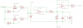
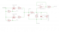
I have designed this circuit that is designed to accept a 0-5V analog signal from a typical automotive pressure sensor, I also want to use a thermistor (a automotive coolant temp sensor) on the same input pin with no external components (voltage source and resistor) so I have added the left hand side of the circuit that can switch a 5V reference voltage through either a 4k or 560R resistor, the reason for the two resistors is because I want to use different sensors of which the specs are vague or no existent and use a wide temp range -10 - 100c.
So when the fets are turned off I want to accept a 0-5v analog signal and when at least one is turned on I want to accept a thermistor that is connected between AIN1 and AGND.
I am using a STM32F which is obviously 3.3v. When I first designed this and asked for help I was told to use a 2.5v reference and supply the VREF+ pin with the 2.5v, so that is why my resistors are set to 10k and 12k. But I am not sure why I can't just connect VREF+ to +3v3 and use a 17k and 33k resistors to get a full 3.3v from 5v?
The input is protected by a SMBJ5.0A as I want to protect it from short circuits to battery positive.
I'm also not sure whether the left hand side of the circuit is going to interfere with my 0-5v signal when not in use?
Ignore the lack of ground symbol, its because I have multiple analog grounds and I kept forgetting what symbol I used for each.
AINB is the output.
Attachments
-
 7.2 KB Views: 19