Collector feedback and output impedance

Thread Starter

Elerion

Joined Sep 11, 2017
125
Hi there.

I found a website that uses Miller's Theorem to analyze a simple collector biased transistor (voltage shunt feedback). There's something about the ouput Z that I don't understand.

https://wiki.analog.com/university/.../chapter-9#example_972_using_miller_s_theorem

By substituting Rf using Miller’s Theorem, Rf appears much smaller at the input, and the input impedance is very much reduced. This is expected. So far, so good.

But Rf appears almost the same at the output (voltage gain is supposed much bigger than one).
According to this, it seems that the output impedance is just this miller-transformed-Rf in parallel with collector resistor.
This way, output impedance gets reduced just a little bit. From 10k to 8,6k or so.

But, the output impedance is supposed to be reduced by a factor of the gain loop.

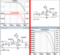
A simple spice simulation shows this clearly. I get around 600 ohm output Z for a 2n2222.

So, what is this Miller's Theorem based analysis missing?

Thanks
 

Jony130

Joined Feb 17, 2009
5,598
Can you show us yor circuit and how did you get Zout around 600Ω?

Are you talking about this circuit ?

1.png

With the voltage gain Av = gm*(Rc || RF) - Rc/(RF + Rc)
 

Thread Starter

Elerion

Joined Sep 11, 2017
125
Are you talking about this circuit ?
Yes
Can you show us yor circuit and how did you get Zout around 600Ω?
Left side, setup for input Z.
Right side, (guess...) setup for output Z.
Just used V/I.

Placing a load at the output, while having an input signal (left side circuit), also leads to a close value of Z (value that leads to half the open circuit output).
 

Attachments

Jony130

Joined Feb 17, 2009
5,598
For the circuit shown her:

2.png


The Rout is equal to:

Rout = (Rc||RF)/(1 + gm*(Rc||RF)*(Rg||RF||rpi) * 1/RF)

As you can see RF appears at the output as a resistor in parallel with Rc resistor.

And Miller's Theorem assumes the we have a ideal voltage amplifer (Rout = 0Ω).

But now we have a much more complicated situation

1 (4).png

Rout = Vx/Ix

Give it a try.
 
Last edited:

Thread Starter

Elerion

Joined Sep 11, 2017
125
Give it a try.
I think I'm doing something wrong.
I start with current law at the output node (all currents going out equal Ix; there're three branches) and the relation of vpi and Vx.
Then, operate.
But this doesn't seem to lead to a good result.

derivation_try1.png
 

Thread Starter

Elerion

Joined Sep 11, 2017
125
For me, your equation looks correct.
My equation apparently differs from yours, but in fact they are pretty close in their results.

Just to use some "real" values, if gm equals 1, rpi=200 (if hfe = 200, reasonable for 2n2222 at low a frequency).
My equation yields 0.5 ohm. Yours, 0.4 ohm.
Using resistor values from the schematic, and supposing gm = 0.04, rpi = 5 kohm (Ic = 1.05 mA):
Both equations yield 467 ohm.

Close enough to the simulation.

And Miller's Theorem assumes the we have a ideal voltage amplifer (Rout = 0Ω).
I understand. But I didn't, until you pointed that out.
In my humble opinion, the article is not clear enough.
It uses Miller's Theorem to transform feedback resistor and calculate input impedance, but doesn't address this issue, and doesn't even mention it. Don't you think? It just ommits the output impedance altogether.
 

Jony130

Joined Feb 17, 2009
5,598
I understand. But I didn't, until you pointed that out.
In my humble opinion, the article is not clear enough.
It uses Miller's Theorem to transform feedback resistor and calculate input impedance, but doesn't address this issue, and doesn't even mention it. Don't you think? It just ommits the output impedance altogether
I'm not an expert on this topic, but maybe they skip it because they know that this does not work for Rout. But for Rin, it works very well.
 

Jony130

Joined Feb 17, 2009
5,598
By the way, is this formula correct? Substraction?
Yes, this formula is correct.

Once again give it try
2a.png

Av = Vo/Vx = (1/RF - gm)/(1/Rf + 1/Rc) = gm*(Rc || Rf) - Rc/(Rf + Rc)

I omitted the minus sign.

o, why does Miller's Theorem don't work for the output but does for the input?
As you said, we don't have an ideal voltage amplifer (Rout > 0). Not only Rout is not zero, but Rin is not very high.
After more thought about this, I think now that my previous answer was wrong.
And Miller's Theorem doesn't work here lays in the fact that now we have negative feedback in the circuit (voltage feedback- parallel input (shunt-shunt type)). Remove the Rg resistor and you will have no negative feedback anymore and Rout = Rc||RF as Miller's Theorem predicts.

Maybe you should ask this question on a General chat. But I'm convinced that the answer is "due to negative feedback".
 
Last edited:
Top