Facebook
 Google
 GitHub
 Linkedin
Hi all!,
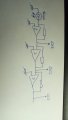
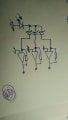
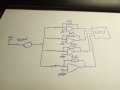
I need to collect data from a sensor, with a wide range of values. I'm thinking in 4 OpAmps, with different Rf in order to have a very widerange of data. I need to collect the data from the all OpAmps at the same time (see attached).
The CPU has ADC, but they are only 12bits resolution. I need more resolution using the embedded ADCs.
My question is: How can I achieve that? Any advices?
Attachments
-
 116.8 KB Views: 9
Last edited: