Facebook
 Google
 GitHub
 Linkedin


Hello AAC,
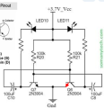
A small two LED blinker circuit was built from
this schematic.
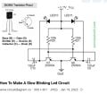
For testing a five-volt adapter was used to confirm operation. Because the circuit is part of wearable
badge it is planned to power the circuit with a coin battery holder which holds two 2032 3 volt coin
batteries.
When the batteries were inserted the battery holder was tested and the DMM showed 0.013 volts
instead of the 6 volts expected.
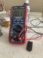
So I reconnected the 5 volt adapter to make sure something
about the DMM was amiss. But the DMM then read 5.1
volts.
There is a switch on the battery holder so I tried moving the switch.
When I moved the switch the result was 0 volts so I moved the switch
again and the reading went back to 0.013 volts.
I tried turning the coins upside down in the holder. This
gave a reading of -0.013 volts.
The battery holder came in a pack of ten so a second holder
was tried with the same result.
I tried holding the DMM probes against one of the bare coins
and got a reading of 3.3 volts.
Is there something about these battery holders I don't understand?
They seem like pretty simple devices so I am stumped as to
why I cannot get them to work.
Thanks
Allen Pitts
A small two LED blinker circuit was built from
this schematic.
For testing a five-volt adapter was used to confirm operation. Because the circuit is part of wearable
badge it is planned to power the circuit with a coin battery holder which holds two 2032 3 volt coin
batteries.
When the batteries were inserted the battery holder was tested and the DMM showed 0.013 volts
instead of the 6 volts expected.
So I reconnected the 5 volt adapter to make sure something
about the DMM was amiss. But the DMM then read 5.1
volts.
There is a switch on the battery holder so I tried moving the switch.
When I moved the switch the result was 0 volts so I moved the switch
again and the reading went back to 0.013 volts.
I tried turning the coins upside down in the holder. This
gave a reading of -0.013 volts.
The battery holder came in a pack of ten so a second holder
was tried with the same result.
I tried holding the DMM probes against one of the bare coins
and got a reading of 3.3 volts.
Is there something about these battery holders I don't understand?
They seem like pretty simple devices so I am stumped as to
why I cannot get them to work.
Thanks
Allen Pitts