CMOS inverter as amplifier, current limiting

Thread Starter

hrs

Joined Jun 13, 2014
394
Hi,

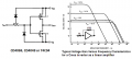
I want to abuse a CD4049UBE for an audio experiment. The power supply will be 15V. I read here that this can bake the inverter (see table, bottom of the page). Since I dont need all 15V of signal head room, can I just stick a resistor between the supply and the VCC pin of the CD4049UBE in order to limit the current? What about a zener between supply and the VCC pin, would that work? If so, that would probably give a more stable supply voltage to the chip than a resistor.

If such a simple fix is possible, I do not have to generate a lower supply voltage in the power supply.
 

Thread Starter

hrs

Joined Jun 13, 2014
394
So that would be generating an extra voltage rail. I would like to avoid a zener regulator because of the current requirement.

I vaguely remember seeing a schematic with something like 100 ohms between the power rail and the VCC pin of a 555. This was supposed to make the 555 hog less current when switching. So I thought a similar thing could be done here, maybe. As for the zener (between the power rail and the VCC pin, not as a regulator) it won't limit the current but it will drop the voltage on the inverter to the point that will only draw a reasonable current, such was my possibly erroneous thought process. Or are such hacks simply not done (if so, why?)?
 

Audioguru again

Joined Oct 21, 2019
6,671
The article you attached does not mention a high current CD4049.
A CD4049 is not supposed to be a linear amplifier because the current in its output transistors is too high and not symmetrical.
It conducts double the current to ground as it does to the positive supply and if you self-bias it the bias voltage is too low.

Use a CD4069 inverter instead. Its current is lower so it does not cook itself and its high and low currents are symmetrical with some of them.

It is not very linear so the output waveform looks squashed on a 'scope with even-harmonics distortion even when not clipping.
Here are some details:
 

Attachments

Thread Starter

hrs

Joined Jun 13, 2014
394
The article you attached does not mention a high current CD4049.
I think this same principle will apply to the CD4049 also:
current.png

Use a CD4069 inverter instead. Its current is lower so it does not cook itself and its high and low currents are symmetrical with some of them.
Yes, I learned this after ordering some CD4049s. Now that I've received them I'll just use the CD4049 for now.

I think I'll just go ahead with my proposed schemes and see what I get.
 

MrAl

Joined Jun 17, 2014
11,388
The article you attached does not mention a high current CD4049.
A CD4049 is not supposed to be a linear amplifier because the current in its output transistors is too high and not symmetrical.
It conducts double the current to ground as it does to the positive supply and if you self-bias it the bias voltage is too low.

Use a CD4069 inverter instead. Its current is lower so it does not cook itself and its high and low currents are symmetrical with some of them.

It is not very linear so the output waveform looks squashed on a 'scope with even-harmonics distortion even when not clipping.
Here are some details:
Hi,

What are the values of the currents when self biased?
 

Thread Starter

hrs

Joined Jun 13, 2014
394
These are the currents that I found. I didn't want to put more than 15 mA through it. Obviously, the zener doesn't work.
Code:
V supply    I supply(A)    I supply(B)    I supply(C)
     4.7            3.5            2.3            0.0
     5.2            6.1            3.0            0.0
     5.6            7.4            3.9            0.0
     6.3           11.2            5.3            0.0
     6.9           15.0            7.1            0.0
     9.0            -             12.2            1.2
    10.0            -             14.5            4.9
cd4049 self biased.png

EDIT: After putting the zener the right way around it starts to look more like what I was expecting. The table has been updated.
 
Last edited:

Wolframore

Joined Jan 21, 2019
2,609
zener diode in forward bias is not being utilized as anything other than a standard diode and drops about 0.7v. I have no idea what your circuit is suppose to do.
 

Thread Starter

hrs

Joined Jun 13, 2014
394
zener diode in forward bias is not being utilized as anything other than a standard diode and drops about 0.7v.
Wow, that was pretty dumb of me. With the zener the correct way around it appears that it does work.

I have no idea what your circuit is suppose to do.
There are three circuits actually, circuits A, B and C. They are supposed to show me how much current a CD4049 draws under various conditions. As you can see there is no way ckt A can run on 15 volts. I was hoping to avoid having to add a 5V rail.

It's starting to look like a bad idea and I should just add the 5V rail, but first the experiment continues.
 

Audioguru again

Joined Oct 21, 2019
6,671
The CD4049 is never symmetrical which causes its output to have clipping or severe distortion on the bottom of its output waveform. Using a 5V supply then its output is fairly linear with an output level of only about 1V peak-to-peak that is only 0.35V RMS. It draws a massive current causing it to heat up causing its spec's to change as it gets hotter.

The CD4069 is typically very symmetrical and its datasheet shows its self-biased output typically drawing 11mA with a 15V supply. Then its output is shown to be fairly linear over an output of 6V peak-to-peak which is 2.12V RMS.
 

Thread Starter

hrs

Joined Jun 13, 2014
394
Yes, I think I'll get a CD4069. The CD4049 just draws too much current. Incidently, since you mention the output drawing current (or I misunderstand), I checked the bias resistor influence on the current draw and 470k or 1M hardly makes a difference. Isn't this the main current path that I'm measuring?
current path.png
 

Audioguru again

Joined Oct 21, 2019
6,671
The bias resistor produces a lot of negative feedback. If the output voltage tries to go down then the resistor causes the input to also go down causing its output to go back up to halfway. Also the opposite.
The value of the resistor has no effect on the DC voltage because the Cmos input draws no current.

Yes, you are correctly showing current through both output Mosfets in series. With a higher supply voltage then the Mosfets have a higher Vgs which causes both of them to conduct more current.
 

Thread Starter

hrs

Joined Jun 13, 2014
394
Why is it that C1 and R2 set the corner frequency of the response here? As I see it both are in series with the signal. But it seems I'm wrong and R2 is somehow in parallel.
 

Attachments

Audioguru again

Joined Oct 21, 2019
6,671
R2 is the load for C1 which is a highpass filter that cuts low frequencies at -6dB per octave.
Since the amplifier is inverting then its input is a virtual ground (almost zero impedance).
 

Thread Starter

hrs

Joined Jun 13, 2014
394
hi hrs,
What is the frequency when the impedance of the 22n equal is to 100k.?
Xc = 1 / (2pi*f*C)
f = 1 / (2pi*Xc*C) = 1 / (6.28*100e3*22e-9) = 72 Hz
I think. [edit] So it's kind of like a voltage divider.[/edit]
R2 is the load for C1 which is a highpass filter that cuts low frequencies at -6dB per octave.
Since the amplifier is inverting then its input is a virtual ground (almost zero impedance).
Oh, right. So that makes R2 parallel to the signal. But then I don't see how C1 is not also parallel.
 

ericgibbs

Joined Jan 29, 2010
18,766
hi,
Not a Voltage divider.

Inv OPA Gain = Rf/Rin , 500k/100k, but Rin at 72Hz is Zcap+R2 = 200k, so Gain is 500k/200k..
E
 
Top