Facebook
 Google
 GitHub
 Linkedin
Hi,
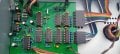
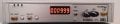
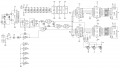
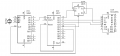
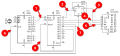
I'm trying to piece together a frequency counter using a circuit from the MC14553 datasheet and a page from a Forrest Mims book. The schematic of what I have so far is attached. The purpose of the frequency counter is to use it with my signal generator so I don't have to use my scope to get an approximate frequency.
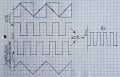
I'm not to sure about the frequency input. As shown the CD4011 may switch as 0.3*VDD or 0.7*VDD so it may not count a 1V p-p sinewave. Surely there needs to be some sort of comparator at the input, with as little hysteresis as you can get away with to make it as sensitive as possible? Or, since my sinewave generator sucks anyway and I'm going to redo it, build a rail to rail output in it to be used by the counter. Is that a common thing to do or should this problem be solved in the counter?
As an aside, how can we find the scan frequency that is set by C13?
I'm trying to piece together a frequency counter using a circuit from the MC14553 datasheet and a page from a Forrest Mims book. The schematic of what I have so far is attached. The purpose of the frequency counter is to use it with my signal generator so I don't have to use my scope to get an approximate frequency.
I'm not to sure about the frequency input. As shown the CD4011 may switch as 0.3*VDD or 0.7*VDD so it may not count a 1V p-p sinewave. Surely there needs to be some sort of comparator at the input, with as little hysteresis as you can get away with to make it as sensitive as possible? Or, since my sinewave generator sucks anyway and I'm going to redo it, build a rail to rail output in it to be used by the counter. Is that a common thing to do or should this problem be solved in the counter?
As an aside, how can we find the scan frequency that is set by C13?
Attachments
-
 212.4 KB Views: 72
 -
 115.2 KB Views: 70