Facebook
 Google
 GitHub
 Linkedin


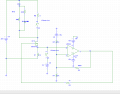
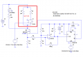
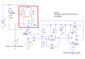
Post the schematic of the circuit you are testing.hi, i am confused because i expected the current at my load to increase when i close the switch however it drops.
This happens when i leave my 5Ω in series with the switch and the LED+resistor( not in series with the load but this time in parallel)
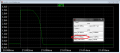
My current starts at a little over 90mA and drops to 75mA when i close my switch, that shouldn't happen it should increase.
I just used a pulsed voltage source to simulate the reset switch. It was simpler than using a voltage-controlled switch.following the schematic you gave me on LT spice, seems i have to download the reset button library because i cant find it.
Are you trying to simulate an actual, accidental fault, caused by a wiring short like i described, or is this a homework assignment, where you have been told where and how the fault occurs? I'm curious about how you came up with the 5Ω resistor.