clearing a fault, using a schmitt trigger a mosfet and a mechanical switch

Thread Starter

newbieateverything

Joined Feb 25, 2013
95
Those two statements are not consistent. Leaving current flowing through the 200Ω resistor is NOT interrupting all the current. Can you see why your posts are so confusing?

So our work is done?
lol yes i see why its confusing now.
i am mostly confused thats why.
I would like the circuit breaker to leave the normal 0.1 amps flowing through the 200Ω..since the resistor (which represents a small motor) would still need some current to work

Our work would be done if i knew why it works with the P channel mosfet and not the N channel.
 

Ron H

Joined Apr 14, 2005
7,063
lol yes i see why its confusing now.
i am mostly confused thats why.
I would like the circuit breaker to leave the normal 0.1 amps flowing through the 200Ω..since the resistor (which represents a small motor) would still need some current to work

Our work would be done if i knew why it works with the P channel mosfet and not the N channel.
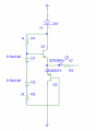
Post your schematic, and maybe we can explain why it works.
 

Thread Starter

newbieateverything

Joined Feb 25, 2013
95
Sorry for the late reply.

The circuit is supposed to start at +15V till the switch closes at 1ms which drops the schmitt trigger O/P to -15V, it stays that way till the 2nd switch closes at 3ms, which forces the schmitt trigger O/P to climb back to +15V

the 2nd switch connected to the 0 supply voltage is there to simulate the action of a reset button.

The way i described it working should work with an N-type mosfet however with N type mosfets my output doesnt go down to -15V when the switch closes at 1ms


Side note: do you know anything about drive circuits?? i am trying to boost the signal coming out of my trigger to ± 20V, to turn on and off the IRF9530N mosfet

A push pull is an example of a drive circuit which can be used to turn my mosfet on or off. Is that correct?

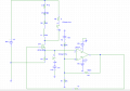
here is what my push pull looks like, it really isnt doing what i want it to do

edit 2: A push pull wont work since the max output it can give is 100%
i need to use something that can output more than the input pulse it receives any ideas?
 

Attachments

Last edited:

Ron H

Joined Apr 14, 2005
7,063
Sorry for the late reply.

The circuit is supposed to start at +15V till the switch closes at 1ms which drops the schmitt trigger O/P to -15V, it stays that way till the 2nd switch closes at 3ms, which forces the schmitt trigger O/P to climb back to +15V

the 2nd switch connected to the 0 supply voltage is there to simulate the action of a reset button.

The way i described it working should work with an N-type mosfet however with N type mosfets my output doesnt go down to -15V when the switch closes at 1ms


Side note: do you know anything about drive circuits?? i am trying to boost the signal coming out of my trigger to ± 20V, to turn on and off the IRF9530N mosfet

A push pull is an example of a drive circuit which can be used to turn my mosfet on or off. Is that correct?

here is what my push pull looks like, it really isnt doing what i want it to do

edit 2: A push pull wont work since the max output it can give is 100%
i need to use something that can output more than the input pulse it receives any ideas?
I ran a simulation on your circuit. It doesn't work for me. Can you post waveforms showing when the switches close and open, and the current through the 5 ohm resistor?
BTW, you have a total of 2.4k (2.2k+200Ω) and an LED in series with the inductor, which I assume represents your motor. This limits the inductor current to about 7.5mA.
Also, you said that the motor current should always be present, and yet you are turning it off with the MOSFET. What's up with that? If you want the motor to run all the time, then it has nothing to do with the fault interrupter. You could leave it out of the schematic.
 

Thread Starter

newbieateverything

Joined Feb 25, 2013
95
I ran a simulation on your circuit. It doesn't work for me. Can you post waveforms showing when the switches close and open, and the current through the 5 ohm resistor?
BTW, you have a total of 2.4k (2.2k+200Ω) and an LED in series with the inductor, which I assume represents your motor. This limits the inductor current to about 7.5mA.
Also, you said that the motor current should always be present, and yet you are turning it off with the MOSFET. What's up with that? If you want the motor to run all the time, then it has nothing to do with the fault interrupter. You could leave it out of the schematic.
Sorry first off no idea why earth i left a 100H inductor there. It shouldn't be there.

Please disregard that.

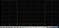
red line is my reference V
purple my input
green my output

I expected this sort of result from an N channel mosfet.

These Voltage readings are from the output, input and ref of the schmitt trigger.
 

Attachments

Ron H

Joined Apr 14, 2005
7,063
Sorry first off no idea why earth i left a 100H inductor there. It shouldn't be there.

Please disregard that.

red line is my reference V
purple my input
green my output

I expected this sort of result from an N channel mosfet.

These Voltage readings are from the output, input and ref of the schmitt trigger.
My sim gives the same results as yours.
You failed to monitor the thing that you are really trying to fix. When you close the fault switch, the current through the 5 ohm resistor goes to 3.4A (you want it to go to zero as soon as the Schmitt trigger output switches low), and stays there until you press the reset switch. It then goes to 4A. See if you can figure out why.

Also, keep in mind that, even if you have a circuit breaker, the fault will recur if you still have the fault switch closed when you try to clear the fault.

Please respond to my previous post:
BTW, you have a total of 2.4k (2.2k+200Ω) and an LED in series with the inductor, which I assume represents your motor. This limits the inductor current to about 7.5mA.
Also, you said that the motor current should always be present, and yet you are turning it off with the MOSFET. What's up with that? If you want the motor to run all the time, then it has nothing to do with the fault interrupter. You could leave it out of the schematic.
I have a circuit that should work for you, but I want you to clear up these issues first.
 

Thread Starter

newbieateverything

Joined Feb 25, 2013
95
My sim gives the same results as yours.
You failed to monitor the thing that you are really trying to fix. When you close the fault switch, the current through the 5 ohm resistor goes to 3.4A (you want it to go to zero as soon as the Schmitt trigger output switches low), and stays there until you press the reset switch. It then goes to 4A. See if you can figure out why.

Also, keep in mind that, even if you have a circuit breaker, the fault will recur if you still have the fault switch closed when you try to clear the fault.

Please respond to my previous post:

I have a circuit that should work for you, but I want you to clear up these issues first.
my motor is represented by the 200 Ω resistor
the 2.2kΩ+diode represents my fault indicating light.
Please ignore the inductor


I mainly just want to show that my circuit wont be interrupted till my switch closes at 1ms causing the fault.
The current through the 200ohm, should remain at 100mA, after the fault is cleared.

Sorry i dont understand why i would want the current going through the 5ohm resistor to go to zero when the trigger outputs a low. The trigger is only outputing a low because the current going through the 5ohm resistor has increased to 3.4

please remember that it is the switch in series with the 5ohm that causes the fault. So the schmitt trigger is responding to this.

could you please show me the circuit you are thinking of .
I am confused all over again
 
Last edited:

Ron H

Joined Apr 14, 2005
7,063
my motor is represented by the 200 Ω resistor
the 2.2kΩ+diode represents my fault indicating light.
Please ignore the inductor


I mainly just want to show that my circuit wont be interrupted till my switch closes at 1ms causing the fault.
The current through the 200mA, should remain at 100mA, after the fault is cleared.
I think you meant "remain at 200mA".
The LED and resistor must be in parallel with the motor, not is series with it. The current through all components in a series circuit is the same.
Sorry i dont understand why i would want the current going through the 5ohm resistor to go to zero when the trigger outputs a low. The trigger is only outputing a low because the current going through the 5ohm resistor has increased to 3.4

could you please show me what you mean. I am confused all over again
When the fault is detected, you want the current through the 5Ω resistor to go to zero, and stay there. To make this happen, the MOSFET must turn off. The circuit breaker (MOSFET) should only be turned back on when the reset button is pressed momentarily.
 

Thread Starter

newbieateverything

Joined Feb 25, 2013
95
I think you meant "remain at 200mA".
The LED and resistor must be in parallel with the motor, not is series with it. The current through all components in a series circuit is the same.
When the fault is detected, you want the current through the 5Ω resistor to go to zero, and stay there. To make this happen, the MOSFET must turn off. The circuit breaker (MOSFET) should only be turned back on when the reset button is pressed momentarily.

yes i meant remain at 200mA

how do i achieve this based on what i have so far

What changes could i make. Or is the entire circuit design wrong?
 
Last edited:

Thread Starter

newbieateverything

Joined Feb 25, 2013
95
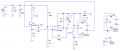
Attached is my solution. You can use the LM324 if you want, but the LM393 will switch faster (It is a real comparator).
I intend to use the LM393 when i build the LM324 is only because i dont have the 393 in my PSPICE package.

Your circuit looks fairly complex. What is the purpose of the flip flop?

In your design the fault occurs, when the switch closes correct

wot software are you using
i like it.
 

Ron H

Joined Apr 14, 2005
7,063
I intend to use the LM393 when i build the LM324 is only because i dont have the 393 in my PSPICE package.

Your circuit looks fairly complex. What is the purpose of the flip flop?

In your design the fault occurs, when the switch closes correct

wot software are you using
i like it.
The flip-flop is needed because of the following:
Before the fault occurs, the gate has to be high. When the fault occurs, the voltage on the sense resistor goes high. Without the latch, and the Schmitt trigger output needs to go low. This is negative feedback, so it won't latch. It will either oscillate, or settle at a current which makes the + and -inputs equal, neither of which is satisfactory.
The flip-flop assures that the circuit will latch, and can't be reset until the flip-flop is reset by the switch on the clear input.

The software is LTspice, a spice simulator from Linear Technology. It's free, and a lot of guys here use it.

EDIT: When the fault occurs due to closing the switch, the MOSFET immediately turns off, and stays off until you push the reset button.
 
Last edited:

shortbus

Joined Sep 30, 2009
10,049
Ron, that is the same thing I was trying to do with my circuit earlier. I left the feed back and pull up out, to get him to ask questions. The lm393 was in a non inverting mode, so it was on until the current got higher over the sense resister. The switch and out put from lm393 went to the and gate. When either one of them dropped out the and gate would shut off the mosfet.
 

Thread Starter

newbieateverything

Joined Feb 25, 2013
95
The flip-flop is needed because of the following:
Before the fault occurs, the gate has to be high. When the fault occurs, the voltage on the sense resistor goes high. Without the latch, and the Schmitt trigger output needs to go low. This is negative feedback, so it won't latch. It will either oscillate, or settle at a current which makes the + and -inputs equal, neither of which is satisfactory.
The flip-flop assures that the circuit will latch, and can't be reset until the flip-flop is reset by the switch on the clear input.

The software is LTspice, a spice simulator from Linear Technology. It's free, and a lot of guys here use it.

EDIT: When the fault occurs due to closing the switch, the MOSFET immediately turns off, and stays off until you push the reset button.
thank you, if i wanted to include some fault indication (LED+resistor) where in the circuit you suggested should i put it.
Also I dont see how the circuit you suggested will actually cause the current in the 200Ω resistor to increase when the switch closes.
Ill draw it up on PSPICE and see what i get

Thank you for your help once again

please send the file i downloaded LT spice 4

is the circuit capable of 0 voltage or current switching? because thats why i was using a dual supply for my schmitt trigger i noticed you are using single supply
 
Last edited:

Ron H

Joined Apr 14, 2005
7,063
thank you, if i wanted to include some fault indication (LED+resistor) where in the circuit you suggested should i put it.
See the attached .asc file. Note that, if the circuit is operating correctly, the LED will only be on for about 4uS, so you probably won't see it unless the circuit is not operating correctly.
Also I dont see how the circuit you suggested will actually cause the current in the 200Ω resistor to increase when the switch closes.
Ill draw it up on PSPICE and see what i get
You said you wanted the current in the 200Ω resistor to remain the same. WTF?:confused::confused:

Thank you for your help once again

please send the file i downloaded LT spice 4

is the circuit capable of 0 voltage or current switching? because thats why i was using a dual supply for my schmitt trigger i noticed you are using single supply
You don't need a negative supply. A MOSFET is off when Vgs=0V. I remember you were trying to come up with some high-voltage driver. All the MOSFET needs to turn on is Vgs≈10V.
I am including a zip file. When you unzip it, save the files in the following folders:

newbie's circuit breaker.asc file to folder LTspiceIV
LM393.sub file to LTspiceIV/lib/sub
LM393.asy file to LTspiceIV/lib/sym/comparators

Then, start LTspiceIV and run the .asc file.
 

Attachments

Thread Starter

newbieateverything

Joined Feb 25, 2013
95
See the attached .asc file. Note that, if the circuit is operating correctly, the LED will only be on for about 4uS, so you probably won't see it unless the circuit is not operating correctly.
You said you wanted the current in the 200Ω resistor to remain the same. WTF?:confused::confused:

You don't need a negative supply. A MOSFET is off when Vgs=0V. I remember you were trying to come up with some high-voltage driver. All the MOSFET needs to turn on is Vgs≈10V.
I am including a zip file. When you unzip it, save the files in the following folders:

newbie's circuit breaker.asc file to folder LTspiceIV
LM393.sub file to LTspiceIV/lib/sub
LM393.asy file to LTspiceIV/lib/sym/comparators

Then, start LTspiceIV and run the .asc file.
:eek: misunderstanding.
I really want the current in the load to increase(hence the fault) then be cleared by the circuit breaker, so the current in the 200Ω returns to its original 100mA once the fault is cleared.

lol my spice version is being difficult it doesnt have CD4000 component
 
Last edited:

Ron H

Joined Apr 14, 2005
7,063
:eek: misunderstanding.
I really want the current in the load to increase(hence the fault) then be cleared by the circuit breaker, so the current in the 200Ω returns to its original 100mA once the fault is cleared.
The current through the 200Ω cannot increase unless you increase the supply voltage. Ohm's Law: I=V/R. I think you need to rethink what you are trying to do, and then explain it.

lol my spice version is being difficult it doesnt have CD4000 component
You can get the CD4000 library from the LTspice Yahoo Group. It is under Files, on the left hand side of the page. You may have to join the group before you can access it.
 

Thread Starter

newbieateverything

Joined Feb 25, 2013
95
The current through the 200Ω cannot increase unless you increase the supply voltage. Ohm's Law: I=V/R. I think you need to rethink what you are trying to do, and then explain it.

You can get the CD4000 library from the LTspice Yahoo Group. It is under Files, on the left hand side of the page. You may have to join the group before you can access it.
really it can't :confused: i guess you are right then.
If the current can't increase in the 200Ω the load.
Then how can i say my circuit breaker is interrupting the circuit to protect the load from a fault current.
If the current in the 200Ω doesn't increase i don't think the circuit needs to be interrupted since the 100mA initially going through the 200Ω is the normal operating current

If this thought process is wrong.
What do you define as a fault current?
please note my default circuit is just the 200Ω being supplied by the 20V

thanks i put the CD4000.lib in my library folder however it still doesnt work
 
Last edited:

Ron H

Joined Apr 14, 2005
7,063
really it can't :confused: i guess you are right then.
If the current can't increase in the 200Ω the load.
Then how can i say my circuit breaker is interrupting the circuit to protect the load from a fault current.
If the current in the 200Ω doesn't increase i don't think the circuit needs to be interrupted since the 100mA initially going through the 200Ω is the normal operating current

If this thought process is wrong.
What do you define as a fault current?
please note my default circuit is just the 200Ω being supplied by the 20V
A fault current is generally caused by a short. With a motor, it would have to be in the wiring external to the motor, or internal to the motor. In either case, if a fault is detected, tripping a circuit breaker, there is no way to keep the current flowing to the load. It must be interrupted until that fault is cleared by eliminating the short circuit. You can simulate this as you had it drawn, with the 5Ω resistor in series with the fault switch, and that combination in parallel with the 200Ω motor. DO NOT put the LED and its current limiting resistor in series with the motor.
Think about your house. Let's say a short developed in the motor in your washing machine. The motor is now defective. It will trip the breaker in your wall panel which monitors that circuit. You must repair or replace the motor before you can reset the breaker. Alternately, let's say the short is in the wall somewhere between the breaker panel and the washer. You still can't run the washer until you have repaired the wiring 9or plugged the washer into another circuit).

thanks i put the CD4000.lib in my library folder however it still doesnt work
You need to put CD4000.lib in your lib/sub folder, not in lib. You also need to download CD4000.zip, and unzip it to lib/sym/digital.
The zip file contains .asy files, which define the symbols, and point to the subcircuits that are the circuitry within the symbol.
 

Thread Starter

newbieateverything

Joined Feb 25, 2013
95
A fault current is generally caused by a short. With a motor, it would have to be in the wiring external to the motor, or internal to the motor. In either case, if a fault is detected, tripping a circuit breaker, there is no way to keep the current flowing to the load. It must be interrupted until that fault is cleared by eliminating the short circuit. You can simulate this as you had it drawn, with the 5Ω resistor in series with the fault switch, and that combination in parallel with the 200Ω motor. DO NOT put the LED and its current limiting resistor in series with the motor.
Think about your house. Let's say a short developed in the motor in your washing machine. The motor is now defective. It will trip the breaker in your wall panel which monitors that circuit. You must repair or replace the motor before you can reset the breaker. Alternately, let's say the short is in the wall somewhere between the breaker panel and the washer. You still can't run the washer until you have repaired the wiring 9or plugged the washer into another circuit).

You need to put CD4000.lib in your lib/sub folder, not in lib. You also need to download CD4000.zip, and unzip it to lib/sym/digital.
The zip file contains .asy files, which define the symbols, and point to the subcircuits that are the circuitry within the symbol.
hi, i am confused because i expected the current at my load to increase when i close the switch however it drops.
This happens when i leave my 5Ω in series with the switch and the LED+resistor( not in series with the load but this time in parallel)
My current starts at a little over 90mA and drops to 75mA when i close my switch, that shouldn't happen it should increase.

following the schematic you gave me on LT spice, seems i have to download the reset button library because i cant find it.
 
Last edited:
Top