 Facebook
 Google
 GitHub
 Linkedin
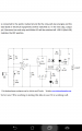
Hi AAC world! I am having a problem with my clap switch. It wouldn't work when I clapped. It only work when I blow or tap the mic.
Can anyone help me adjust its sensitivity.
Thank You!
Can anyone help me adjust its sensitivity.
Thank You!
Attachments
-
 108.9 KB Views: 48


