CKP-CPOL CKE-CPHA etc on an 18F46K20 PIC (Oshonsfoft)

sagor

Joined Mar 10, 2019
1,053
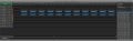
Difference between NSASPOOK's scope and Camerart is NAS's data is read on rising edge, Camerart is read on dropping edge of clock. Those are two different configurations...
 

Thread Starter

camerart

Joined Feb 25, 2013
3,847
Difference between NSASPOOK's scope and Camerart is NAS's data is read on rising edge, Camerart is read on dropping edge of clock. Those are two different configurations...
Hi S,
True, I've tried all of the combinations, and can't get the clock to be low and rise on the first BIT, so far.
I see that I have been mistaken with MODE 0 0 which I'll correct, but I am sure I've covered it in the past.
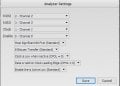
I'll correct my error, and post the analyser and OSC views again.
C
 

nsaspook

Joined Aug 27, 2009
16,450
Hi M,
You're dead on topic, as I'm also confused :)
Here is the CKE section from the PIC D/S
--------------------------------------------------------
bit 6 CKE: SPI Clock Select bit(1)
1 = Output data changes on clock transition from active to idle
0 = Output data changes on clock transition from idle to active
-----------------------------------------------------
I have set CKE to 0, as the CLK is set to LOW idle. It's confusing!
I'll have to re-think.
C
The register bits (and datasheet descriptions) can be confusing (and language functions or defines to set modes) as to what SPI mode is actually being set. CKP-CPOL CKE-CPHA are not necessarily equivalent for setting the SPI mode.

Trust your scope, looking at the physical data line signals for what's being set.
 

Thread Starter

camerart

Joined Feb 25, 2013
3,847
The register bits (and datasheet descriptions) can be confusing (and language functions or defines to set modes) as to what SPI mode is actually being set. CKP-CPOL CKE-CPHA are not necessarily equivalent for setting the SPI mode.

Trust your scope, looking at the physical data line signals for what's being set.
Hi N,
Here's MODE 0 as #17 (Which clarifies the settings)

--------------------------------------------------------------------------
PIC MODE settings:
'*******************************************************
'* *
'* START UP SPI ROUTINE *
'* *
'*******************************************************
Proc init_spi() 'PIC 18F46K20

TRISC.3 = 0 'SCK to Slave ****** output *******
TRISC.5 = 0 'MOSI ****** output *******
TRISC.4 = 1 'MISO ****** input *******

SSPSTAT.SMP = 0 'SMP 0 = Input data sampled at middle of data output time
SSPSTAT.CKE = 1 '+ CKP = 0 = MODE 0 &
'CKE= 0 Output data changes on clock transition from idle to active
'CKE= 1 Output data changes on clock transition from active to idle
'Polarity of clock state is set by the CKP bit of the SSPCON1 register.
'SSPSTAT 'D/A I2C
'SSPSTAT 'P I2C
'SSPSTAT 'S I2C
'SSPSTAT 'R/W I2C
'SSPSTAT 'UA I2C
'SSPSTAT 'BF I2C

SSPCON1 = 0 'RESET THE CONTROL REGISTER **************************************ADDED
SSPCON1.WCOL = 0 'Collision detect
SSPCON1.SSPOV = 0 'Overflow
'SSPCON1.SSPEN = 1 'Configure SCK,SD0,SDI,/SS ** HAS TO BE 1. To reset or reconfigure SPI mode, clear the SSPEN bit,
'reinitialize the sspcon registers And Then set the SSPEN Bit from the datasheet
SSPCON1.CKP = 0 '(0 = Idle state for clock is a low level)
'SSPCON1.CKP = 1 '(1 = Idle state for clock is a high level)
SSPCON1.SSPM3 = 0 '0010 = SPI Master mode, clock = FOSC/64
SSPCON1.SSPM2 = 0
SSPCON1.SSPM1 = 1 'MASTER MODE
SSPCON1.SSPM0 = 0
'^^^^^ MOVED ^^^^^^^^^^^^^^^^^^^^&
SSPCON1.SSPEN = 1 'Configure SCK,SD0,SDI,/SS ** HAS TO BE 1. To reset or reconfigure SPI mode, clear the SSPEN bit,

End Proc
------------------------------------------------------------------------------------------------
I had this set before, but the analyser was incorrect.
Thanks for all of you're persistance :)
C
 

Attachments

Top