CKP-CPOL CKE-CPHA etc on an 18F46K20 PIC (Oshonsfoft)

Thread Starter

camerart

Joined Feb 25, 2013
3,730
Hi,
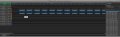
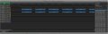
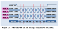
I've been trying to program a PIC with the correct CLK timings to achieve this shape: (See READ-WRITE)
I've posted 2x examples from a data analyser.
1/BYTES in sequence with correct? timing.
2/The Clock polarity is set to IDLE LOW (as READ WRITE) but it starts way in front of the BYTE READing section. Does this matter?
Camerart.
 

Attachments

Thread Starter

camerart

Joined Feb 25, 2013
3,730
Most common SPI devices are mode 0 or 3 auto-detected from what the master sends after CS/SS goes low.
View attachment 277719

Your device is likely mode 0.
http://ww1.microchip.com/downloads/en/devicedoc/40001303h.pdf
page 185
Hi N,
There are 2x devices the PIC and the NEO-8, both need to be set. The analyser also needs to match.
At first I changed the GPS to match my other peripherals, but when I couldn't get results from MISO, I made a new program where I use the GPS D/S example that I posted.
If you look at my examples from the analyser, the only way I can get the READ DATA when the clock transitions in the middle of the BIT, (Shown by the arrows) the clock has to be set as CLK LOW image, so it isn't asctually as the READ WRITE example.
does this matter?
(If this isn't clear, i'll try again)
C
 

Thread Starter

camerart

Joined Feb 25, 2013
3,730
Hi,
I have improved the shape of the clock square wave, but it's still not quite like the D/S, as it goes HIGH-LOW before the first BIT.
Again, does this matter?
The reason I'm trying to be accurate is that I can't get the GPS to work. I've been trying on and off since March, and looking for small errors, I may be making.
C
 

Attachments

nsaspook

Joined Aug 27, 2009
13,315
Slow your SPI clock speed way down. What's the MAX SPI speed for the device? A lot of SPI interfaces are software driven so the max speed might only be 100khz or lower.

Normally I would configure the master with clock idle low and data idle high for a unknown SPI device with the clock at maybe 25khz when looking for a response to a SPI dummy transmission of 0xFF after a device power cycle.
 

Thread Starter

camerart

Joined Feb 25, 2013
3,730
Slow your SPI clock speed way down. What's the MAX SPI speed for the device? A lot of SPI interfaces are software driven so the max speed might only be 100khz or lower.

Normally I would configure the master with clock idle low and data idle high for a unknown SPI device with the clock at maybe 25khz when looking for a response to a SPI dummy transmission of 0xFF after a device power cycle.
Hi N,
The maximum SPI clock frequency is 5.5 MHz on the NEO-8, I have set the PIC output to be as slow as possible.
Thanks.
C
 

nsaspook

Joined Aug 27, 2009
13,315
Hi N,
I've tried all of the MODES, but can't get the exact shape in the analyser as the D/S.
EDITED
C
Can you post what mode 0 looks like on the analyzer. What matters is not the exact shape, what matters is edge transition timing from one level to the other on CLOCK and DATA.
https://rheingoldheavy.com/spi-signals/
The good thing to know about the various SPI modes, is that you just have to dig into the datasheet for your particular component to find out what modes it supports, and then use that one. Further, 90% of the time you’ll discover that the chips support MODE0 and MODE3, because in both of those instances, as you can see in the mode diagram above, the data is sampled on the rising edge of the clock pulse.
 

Thread Starter

camerart

Joined Feb 25, 2013
3,730
Can you post what mode 0 looks like on the analyzer. What matters is not the exact shape, what matters is edge transition timing from one level to the other on CLOCK and DATA.
https://rheingoldheavy.com/spi-signals/
Hi N,
Here is the analyser output, and settings from the PIC.
Plus the analyser settings to read it. It can be seen that the analyser needs to be set incorrectly, which is either an error by me somewhere or possibly a bug somewhere?
C
 

Attachments

Last edited:

Thread Starter

camerart

Joined Feb 25, 2013
3,730
Hi,
It's possible that when I program the NEO-8s in Ucenter, it isn't remembering all of the settings, although I can see some settings are remembered.
The latest NEO-8s are from a recognised source, so I am pretty sure they are genuine, and have flash memory under the GND screen.
C
 

nsaspook

Joined Aug 27, 2009
13,315
This is what mode 0 with your decoded data values should look like on a oscope with SPI decoding.
PXL_20221007_165006467.jpg
PXL_20221007_165923730.jpg
PXL_20221007_165803132.jpg

If you need to change your analyzer POL and PHA to something other than 0 and 0 to decode correctly, your not actually sending SPI MODE 0 from the processor.
 

MMcLaren

Joined Feb 14, 2010
861
I hope this isn't off-topic. Can someone confirm the relationship between Microchip 'CKP' and 'CKE' settings and the 'CPOL' and 'CPHA' modes in the chart below, please?

TIA. Mikespi modes.png
 

Attachments

Thread Starter

camerart

Joined Feb 25, 2013
3,730
This is what mode 0 with your decoded data values should look like on a oscope with SPI decoding.

If you need to change your analyzer POL and PHA to something other than 0 and 0 to decode correctly, your not actually sending SPI MODE 0 from the processor.
Hi N,
You're correct! Here is an OSC view of the SCK and MOSI.
I'll look into it.
C
 

Attachments

Last edited:

Thread Starter

camerart

Joined Feb 25, 2013
3,730
I hope this isn't off-topic. Can someone confirm the relationship between Microchip 'CKP' and 'CKE' settings and the 'CPOL' and 'CPHA' modes in the chart below, please?

TIA. MikeView attachment 277904
Hi M,
You're dead on topic, as I'm also confused :)
Here is the CKE section from the PIC D/S
--------------------------------------------------------
bit 6 CKE: SPI Clock Select bit(1)
1 = Output data changes on clock transition from active to idle
0 = Output data changes on clock transition from idle to active
-----------------------------------------------------
I have set CKE to 0, as the CLK is set to LOW idle. It's confusing!
I'll have to re-think.
C
 
Top