circuit to breadboard

WBahn

Joined Mar 31, 2012
32,706
Maybe.

We can't see exactly which holes, relative to the pot pins, some of the wires are going into.

We can't see what the specific part number is for the MOSFET, so we can't know the pinout.

We can't see the legend on the pot, so we can't know the pinout.
 

Thread Starter

fups

Joined Sep 28, 2024
2
Maybe.

We can't see exactly which holes, relative to the pot pins, some of the wires are going into.

We can't see what the specific part number is for the MOSFET, so we can't know the pinout.

We can't see the legend on the pot, so we can't know the pinout.
 

Attachments

dl324

Joined Mar 30, 2015
18,220
Welcome to AAC!
I think i did this correctly, can i get any feedback on my breadboard.
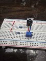
The drain resistor looks like 110 ohms to me because of the spacing between the brown band on the power side of the resistor and the black bands.

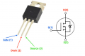
You have that resistor connected to the gate of the MOSFET (I haven't seen any that aren't GDS). That means the junction of the 100k and the pot is connected to the drain, not the gate.

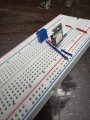
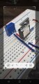
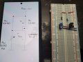
When I breadboard, I try to align the resistors in the same direction so it's easy to read their color codes:
discreteMosfetRegulatorFinalAsBuilt.jpg
I also use a lead former on the leads.
 
Top